
Toyota Sienna Service Manual: Evaporative Emission Control System Incorrect Purge Flow
DTC P0441 Evaporative Emission Control System Incorrect Purge Flow
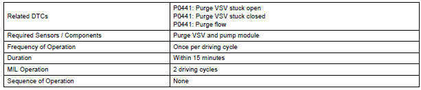
DTC SUMMARY
DESCRIPTION
The circuit description can be found in the EVAP (Evaporative Emission) System.
INSPECTION PROCEDURE
Refer to the EVAP System.
MONITOR DESCRIPTION
The two monitors, Key-Off and Purge Flow, are used to detect malfunctions relating to DTC P0441. The Key-off monitor is initiated by the ECM internal timer, known as the soak timer, 5 hours*1 after the ignition switch is turned off. The purge flow monitor runs while the engine is running.
1. KEY-OFF MONITOR
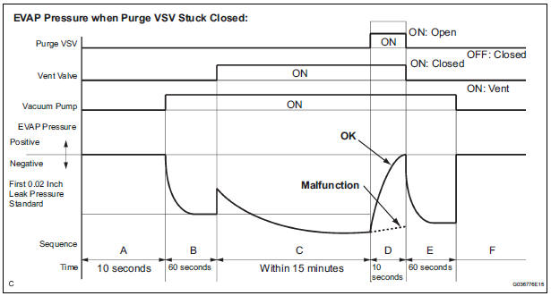
5 hours*1 after the ignition switch is turned off, the electric vacuum pump creates negative pressure (vacuum) in the EVAP (Evaporative Emission) system. The ECM monitors for leaks and actuator malfunctions based on the EVAP pressure.
HINT: *1: If the engine coolant temperature is not below 35C (95F) 5 hours after the ignition switch is turned off, the monitor check starts 2 hours later. If it is still not below 35C (95F) 7 hours after the ignition switch is turned off, the monitor check starts 2.5 hours later.
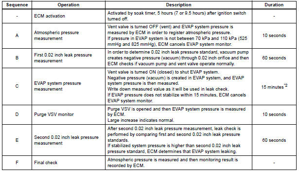
*2: If only a small amount of fuel is in the fuel tank, it takes longer for the EVAP pressure to stabilize.
- Purge VSV stuck open
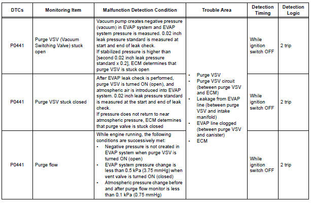
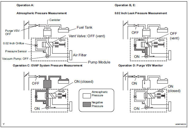
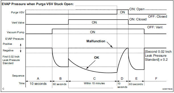
In operation C, the vacuum pump creates negative pressure (vacuum) in the EVAP (Evaporative Emission) system. The EVAP system pressure is then measured by the ECM using the pressure sensor. If the stabilized system pressure is higher than [second 0.02 inch leak pressure standard x 0.2], the ECM interprets this as the purge VSV (Vacuum Switching Valve) being stuck open.The ECM illuminates the MIL and sets the DTC (2 trip detection logic).
- Purge VSV stuck closed
In operation D, the pressure sensor measures the EVAP (Evaporative Emission) system pressure. The pressure measurement for purge VSV monitor is begun when the purge VSV is turned on (open) after the EVAP leak check. When the measured pressure indicates an increase of 0.3 kPa (2.25 mmHg) or more, the purge VSV is functioning normally. If the pressure does not increase, the ECM interprets this as the purge VSV being stuck closed. The ECM illuminates the MIL and sets the DTC (2 trip detection logic).
2. PURGE FLOW MONITOR
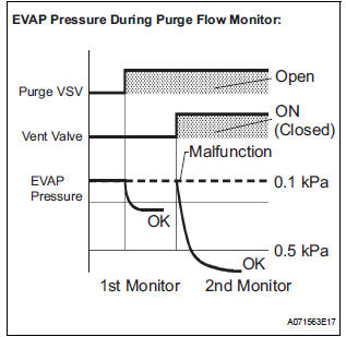
The purge flow monitor consists of the two step monitors.
The 1st monitor is conducted every time and the 2nd monitor is activated if necessary.
- The 1st monitor
While the engine is running and the purge VSV (Vacuum Switching Valve) is on (open), the ECM monitors the purge flow by measuring the EVAP pressure change. If negative pressure is not created, the ECM begins the 2nd monitor. - The 2nd monitor
The vent valve is turned on (closed) and the EVAP pressure is then measured. If the variation in the pressure is less than 0.5 kPa (3.75 mmHg), the ECM interprets this as the purge VSV being stuck closed, and illuminates the MIL and sets DTC P0441 (2 trip detection logic).
Atmospheric pressure check: In order to ensure reliable malfunction detection, the variation between the atmospheric pressures, before and after conduction of the purge flow monitor, is measured by the ECM.
MONITOR STRATEGY
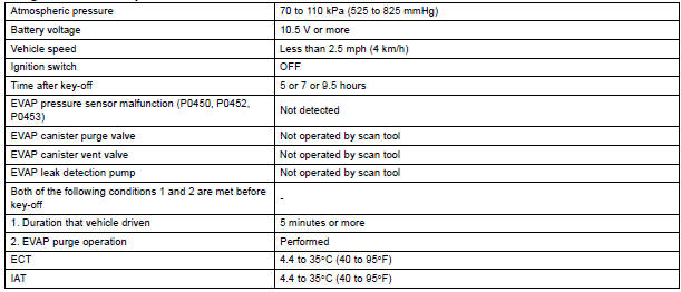
TYPICAL ENABLING CONDITIONS
All:

Purge flow:
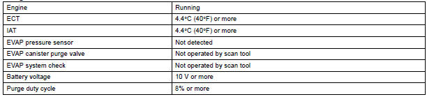
Purge VSV stuck open and closed:
Key-off monitor sequence 1 to 8
1. Atmospheric pressure measurement

2. First reference pressure measurement

3. EVAP canister vent valve close stuck check

4. Vacuum introduction

5. EVAP canister purge valve close stuck check

6. Second reference pressure measurement

7. Leak check

8. Atmospheric pressure measurement

TYPICAL MALFUNCTION THRESHOLDS
Purge flow:

EVAP VSV stuck open:

EVAP VSV stuck closed:

MONITOR RESULT
Refer to CHECKING MONITOR STATUS
 Evaporative Emission System
DTC P043E Evaporative Emission System Reference Orifice
Clog Up
DTC P043F Evaporative Emission System Reference Orifice
High Flow
DTC P2401 Evaporative Emission System Leak Detection
Pump Control ...
 Evaporative Emission Control System Pressure
DTC P0450 Evaporative Emission Control System Pressure
Sensor / Switch
DTC P0451 Evaporative Emission Control System Pressure
Sensor Range / Performance
DTC P0452 Evaporative Emission Control Syst ...
Other materials:
Removal
1. RECOVER REFRIGERANT FROM REFRIGERATION
SYSTEM (See page AC-172)
2. REMOVE NO. 2 AIR CLEANER INLET (See page EM-
28)
3. REMOVE FRONT BUMPER ASSEMBLY (See page
ET-3)
4. DISCONNECT DISCHARGE HOSE SUB-ASSEMBLY
(a) Remove the bolt and disconnect the discharge hose
sub-assembly from the coo ...
Inspection
1. INSPECT STEERING PAD SWITCH LH (w/o
Navigation System)
Measure the resistance according to the values in
the table below.
Standard resistan
If the result is not as specified, replace the steering
pad switch LH.
2. INSPECT STEERING PAD SWITCH RH (w/ Navigation
System)
...
Radio and Navigation Assembly Power Source Circuit
DESCRIPTION
This is the power source circuit to operate the radio and navigation
assembly.
WIRING DIAGRAM
INSPECTION PROCEDURE
1 INSPECT RADIO AND NAVIGATION ASSEMBLY
Disconnect the radio and navigation assembly connector
R15.
Measure the resistance according to the value ...
