Toyota Sienna Service Manual: Front Fog Light Circuit
DESCRIPTION
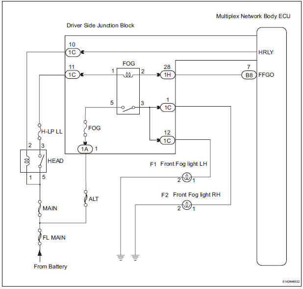
The Multiplex network body ECU controls FOG relay when signal is received from headlight dimmer switch assembly.
WIRING DIAGRAM
INSPECTION PROCEDURE
1 PERFORM ACTIVE TEST BY INTELLIGENT TESTER
- Connect the intelligent tester to DLC3.
- Turn the ignition switch ON and push the intelligent tester main switch ON.
- Select the item below in the ACTIVE TEST and then check that the relay operates.
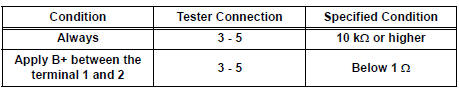
2 INSPECT FOG LIGHT RELAY
- Inspect fog light relay continuity.
Standard
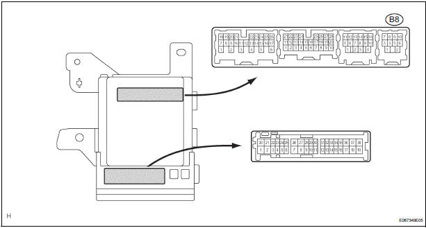
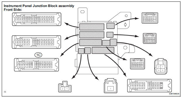
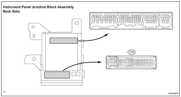
3 INSPECT INSTRUMENT PANEL JUNCTION BLOCK ASSEMBLY
- Measure voltage between the terminal B8-7 of the multiplex network body ECU in the instrument panel junction block assembly and body ground.
Voltage
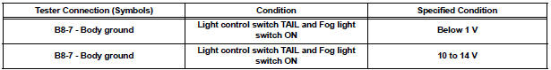
4 INSPECT INSTRUMENT PANEL JUNCTION BLOCK ASSEMBLY
- Remove the instrument panel junction block assembly.
- Measure voltage between each of the terminals as shown in the chart below.
Voltage

REPAIR OR REPLACE HARNESS OR CONNECTOR
 DRL Relay Circuit
DESCRIPTION
The Multiplex network body ECU controls the DRL No.2 relay
WIRING DIAGRAM
INSPECTION PROCEDURE
1 PERFORM ACTIVE TEST BY INTELLIGENT TESTER
Connect the intelligent tester to DLC ...
 Light Control Switch Circuit
DESCRIPTION
This circuit detects the state of the headlight dimmer switch.
WIRING DIAGRAM
INSPECTION PROCEDURE
1 READ VALUE OF INTELLIGENT TESTER
Connect the intelligent tester to DLC3.
...
Other materials:
Compressor Solenoid Circuit
DESCRIPTION
In this circuit, the compressor receives a refrigerant compression demand
signal from the A/C amplifier.
Based on this signal, the compressor changes the amount of compressor output.
WIRING DIAGRAM
INSPECTION PROCEDURE
1 INSPECT A/C COMPRESSOR
(a) Disconnect the A/C com ...
Installation
1. INSTALL FRONT SHOULDER BELT ANCHOR
ADJUSTER ASSEMBLY
Install the front shoulder belt anchor adjuster
assembly with the bolt.
Torque: 42 N*m (430 kgf*cm, 31 ft.*lbf)
2. INSTALL CENTER PILLAR UPPER GARNISH
3. INSTALL FRONT SEAT OUTER BELT ASSEMBLY
NOTICE:
Do not disassemble ...
If your vehicle has to
be stopped in an
emergency
Only in an emergency, such as if it becomes impossible to stop
the vehicle in the normal way, stop the vehicle using the following
procedure:
Steadily step on the brake pedal with both feet and firmly depress it.
Do not pump the brake pedal repeatedly as this will increase the effort
requi ...
