Toyota Sienna Service Manual: Installation
1. INSTALL FRONT SHOCK ABSORBER WITH COIL SPRING
(a) Install the front shock absorber with coil spring as shown in the illustration.
(b) Install the 3 nuts to the upper side of the front shock absorber with coil spring.
Torque: 80 N*m (816 kgf*cm, 59 ft.*lbf)
(c) Install the 2 bolts and 2 nuts to the lower side of the front shock absorber with coil spring.
Torque: 210 N*m (2,140 kgf*cm, 155 ft.*lbf)
NOTICE: When installing the bolt, hold the nut not to rotate.
(d) Fully tighten the lock nut.
Torque: 49 N*m (500 kgf*cm, 36 ft.*lbf)
(e) Install the front flexible hose No.1 and speed sensor front LH with the bolt.
Torque: 19 N*m (189 kgf*cm, 14 ft.*lbf)
2. INSTALL FRONT STABILIZER LINK ASSEMBLY LH
(a) Install the front stabilizer link assembly LH with the nut.
Torque: 74 N*m (755 kgf*cm, 55 ft.*lbf)
HINT: If the ball joint turns together with the nut, use a hexagon (6 mm) wrench to hold the stud.
3. INSTALL COWL TOP PANEL SUB-ASSEMBLY OUTER FRONT
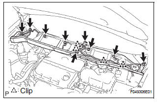
(a) Install the cowl top brace and cowl top panel subassembly outer front with the 9 bolts.
Torque: 7.5 N*m (76 kgf*cm, 66 in.*lbf) (b) Connect the wire harness to the cowl top panel subassembly outer front.
4. INSTALL WINDSHIELD WIPER MOTOR & LINK ASSEMBLY
HINT: (See page WW-3)
5. INSTALL FR WIPER ARM LH
HINT: (See page WW-3)
6. INSTALL FR WIPER ARM RH
HINT: (See page WW-3)
7. INSTALL FRONT WHEEL Torque: 103 N*m (1,050 kgf*cm, 76 ft.*lbf)
8. INSPECT AND ADJUST FRONT WHEEL ALIGNMENT
HINT: (See page SP-4)
 Reassembly
1. INSTALL SHOCK ABSORBER ASSEMBLY FRONT LH
2. INSTALL FRONT COIL SPRING INSULATOR LOWER
LH
(a) Install the front coil spring insulator lower LH onto
the shock absorber assembly front LH.
3. INST ...
 Disposal
1. DISPOSE OF SHOCK ABSORBER ASSEMBLY FRONT LH
HINT:
Dispose the RH side by the same procedures as the LH
side.
(a) Fully extend the shock absorber rod.
(b) Using a drill, make a hole in the cy ...
Other materials:
Installation
1. INSTALL NO. 1 REAR DIFFERENTIAL SUPPORT
(a) Install the No. 1 rear differential support to the rear
differential carrier assembly with the 2 bolts and 2
nuts.
Torque: 85 N*m (867 kgf*cm, 63 ft.*lbf)
HINT:
Hold the bolt and tighten the nut.
2. INSTALL REAR DIFFERENTIAL DYNAMIC DAMPER
...
TS and CG Terminal Circuit
DESCRIPTION
In the sensor check mode, a malfunction of the speed sensor that cannot be
detected when the vehicle is
stopped is detected while driving.
Transition to the sensor check mode can be performed by connecting terminals TS
and CG of the DLC3
and turning the ignition switch from off ...
Oxygen (A/F) Sensor Signal Stuck
HINT:
Although the DTC titles say oxygen sensor, these DTCs relate to the
Air-Fuel Ratio (A/F) sensor.
Sensor 1 refers to the sensor mounted in front of the Three-Way
Catalytic Converter (TWC) and
located near the engine assembly.
DESCRIPTION
The A/F sensor generates a voltage* ...
