Toyota Sienna Service Manual: Front No. 1 speaker
COMPONENTS
ON-VEHICLE INSPECTION
1. INSPECT FRONT NO.1 SPEAKER
HINT: Remove interior parts so that the front No.1 speaker can be seen.
- Check the speaker installation.
OK: The speaker is securely installed.
If the result is not as specified, reinstall the front No.1 speaker.
- Visually check the speaker.
OK: The cone paper of the speaker is not torn.
If the result is not as specified, replace the front No.1 speaker.
- Speaker resistance check
- Disconnect the front No.1 speaker connector.
- Measure the resistance between the terminals of the speaker.
Standard resistance:
6 Speaker system:
Approximately 4 Ω
10 Speaker system:
4 to 6 Ω
If the result is not as specified, replace the front No.1 speaker.
REMOVAL
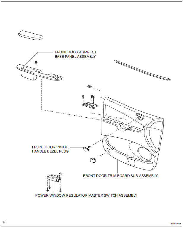
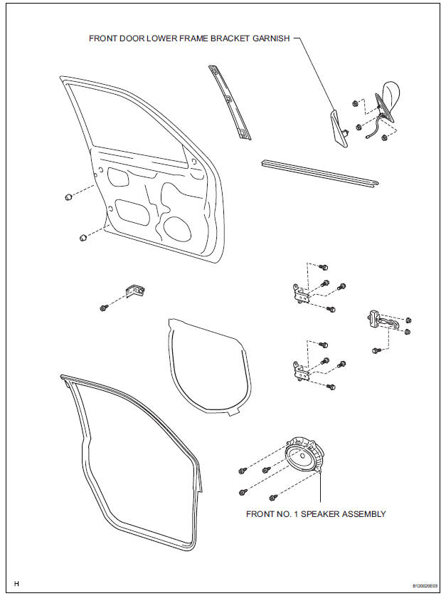
1. REMOVE FRONT DOOR LOWER FRAME BRACKET GARNISH
2. REMOVE FRONT DOOR INSIDE HANDLE BEZEL PLUG
3. REMOVE POWER WINDOW REGULATOR MASTER SWITCH ASSEMBLY
4. REMOVE FRONT DOOR ARMREST BASE PANEL ASSEMBLY
5. REMOVE FRONT DOOR TRIM BOARD SUBASSEMBLY
6. REMOVE FRONT NO. 1 SPEAKER ASSEMBLY
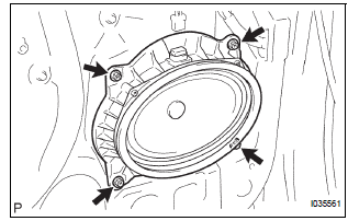
- Disconnect the connector.
- Remove the 4 screws and front No. 1 speaker assembly.
INSTALLATION
1. INSTALL FRONT NO. 1 SPEAKER ASSEMBLY
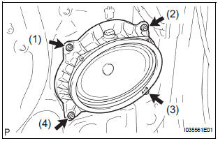
- Install the front No. 1 speaker assembly with the 4
screws.
NOTICE: Tighten the screws in order shown in the illustration to install the front No. 1 speaker assembly.
- Connect the connector.
2. INSTALL FRONT DOOR TRIM BOARD SUBASSEMBLY
3. INSTALL FRONT DOOR ARMREST BASE PANEL ASSEMBLY
4. INSTALL POWER WINDOW REGULATOR MASTER SWITCH ASSEMBLY
5. INSTALL FRONT DOOR INSIDE HANDLE BEZEL PLUG
6. INSTALL FRONT DOOR LOWER FRAME BRACKET GARNISH
 Window glass antenna wire
INSPECTION
1. INSPECT WINDOW GLASS ANTENNA WIRE
Inspect the wind glass antenna wire.
NOTICE:
When cleaning the glass, use a soft, dry cloth,
and wipe the glass in the direction of the ...
 Front No. 2 speaker
COMPONENTS
ON-VEHICLE INSPECTION
1. INSPECT FRONT NO.2 SPEAKER
HINT:
Remove interior parts so that the front No.2 speaker can
be seen.
Check the speaker installation.
OK:
The sp ...
Other materials:
Parts location
SYSTEM DIAGRAM
...
Roof luggage carrier (if equipped)
Roof luggage carrier components
Roof rails
Cross rails
Adjusting the position of cross rails
Turn the knobs counterclockwise
to release the cross
rails.
Slide the cross rails to the
appropriate position for loading
luggage and turn the
knobs clockwise to tigh ...
Perform monitor drive pattern
The monitor results and test values can be checked with
the OBD II scan tool or the intelligent tester. The engine
control module (ECM) monitors the emissions-related
components such as the thermostat, catalyst converter
and evaporative emissions (EVAP), and determines
whether they are function ...
