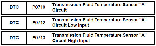
Toyota Sienna Service Manual: Transmission Fluid Temperature Sensor "A"
DESCRIPTION
The ATF (Automatic Transmission Fluid) temperature sensor converts the fluid temperature into a resistance value which is input into the ECM.
The ECM applies a voltage to the temperature sensor through ECM terminal THO1.
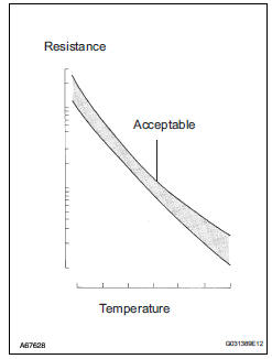
The sensor resistance changes with the transmission fluid temperature. As the temperature becomes higher, the sensor resistance decreases.
One terminal of the sensor is grounded so that the sensor resistance decreases and the voltage goes down as the temperature becomes higher.
The ECM calculates the fluid temperature based on the voltage signal.

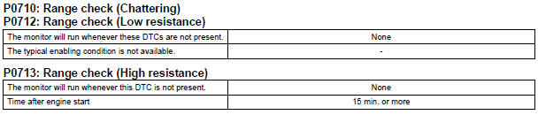
MONITOR DESCRIPTION
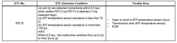
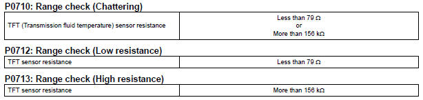
These DTCs indicate an open or short in the automatic transmission fluid (ATF) temperature sensor (TFT sensor) circuit. The automatic transmission fluid (ATF) temperature sensor converts ATF temperature to an electrical resistance value. Based on the resistance, the ECM determines the ATF temperature, and the ECM detects an opens or shorts in the ATF temperature circuit. If the resistance value of the ATF temperature is less than 79 Ω *1or more than 156 kΩ *2, the ECM interprets this as a fault in the ATF sensor or wiring. The ECM will turn on the MIL and store the DTC.
*1: 150°C (302°F) or more is indicated regardless of the actual ATF temperature.
*2: -40°C (-40°F) is indicated regardless of the actual ATF temperature.
HINT: The ATF temperature can be checked on the OBD II scan tool or intelligent tester display.
MONITOR STRATEGY
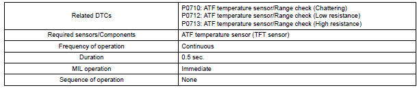
TYPICAL ENABLING CONDITIONS
TYPICAL MALFUNCTION THRESHOLDS
COMPONENT OPERATING RANGE

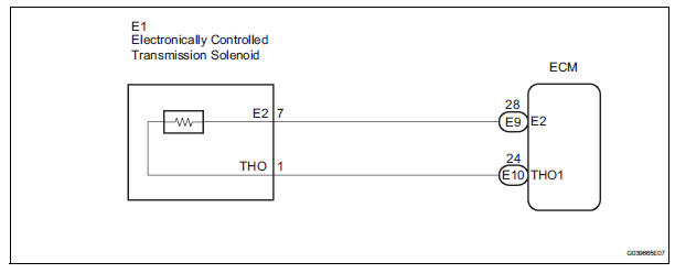
WIRING DIAGRAM
INSPECTION PROCEDURE
HINT: Using the intelligent tester to read the DATA LIST allows the values or states of switches, sensors, actuators and other items to be read without removing any parts. This non-intrusive inspection can be very useful because intermittent conditions or signals may be discovered before parts or wiring is disturbed. Reading the DATA LIST information early in troubleshooting is one way to save diagnostic time.
| NOTICE: In the table below, the value listed under "Normal Condition" are reference values. Do not depend solely on these reference values when deciding whether apart is faulty or not. |
1. READ DATA LIST
(a) Warm up the engine.
(b) Turn the ignition switch off.
(c) Connect the intelligent tester together with the CAN VIM (controller area network vehicle interface module) to the DLC3.
(d) Turn the ignition switch to the ON position.
(e) Turn on the tester.
(f) Select the item "DIAGNOSIS / ENHANCED OBD II / DATA LIST".
(g) According to the display on the tester, read the "DATA LIST".

HINT: When DTC P0712 is output and OBD II scan tool or intelligent tester output is 150°C (302°F), there is a short circuit.
When DTC P0713 is output and OBD II scan tool or intelligent tester output is -40°C (-40°F), there is an open circuit.
Measure the resistance between terminal THO1 (THO) and body ground.
HINT: If a circuit related to the ATF temperature sensor become open, P0713 is immediately set (in 0.5 second).
When P0713 is set, P0711 cannot be detected.
It is not necessary to inspect the circuit when P0711 is set.
1 INSPECT TRANSMISSION WIRE (ATF TEMPERATURE SENSOR)
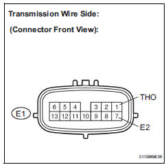
(a) Disconnect the transmission wire connector from the transaxle.
(b) Measure the resistance according to the value(s) in the table below.
Standard resistance
HINT:
If the resistance is out of the specified range with either
the ATF temperature shown in the table below, the
driveability of the vehicle may decrease.


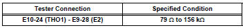
2 CHECK HARNESS AND CONNECTOR (TRANSMISSION WIRE - ECM)

(a) Connect the transmission wire connector to the transaxle.
(b) Disconnect the ECM connectors.
(c) Measure the resistance according to the value(s) in the table below.
Standard resistance
(d) Measure the resistance according to the value(s) in the table below.
Standard resistance (Check for short)


REPLACE ECM
 Transmission Range Sensor Circuit Malfunction
(PRNDL Input)
Transmission Range Sensor Circuit Malfunction
(PRNDL Input)
DESCRIPTION
The park/neutral position switch detects the shift lever position and sends
signals to the ECM.
MONITOR DESCRIPTION
These DTCs indicate a problem with the park/neutral position ...
 Transmission Fluid Temperature Sensor "A"
Performance
Transmission Fluid Temperature Sensor "A"
Performance
DESCRIPTION
The ATF (Automatic Transmission Fluid) temperature sensor converts the fluid
temperature into a
resistance value which is input into the ECM.
MONITOR DESCRIPTION
The ATF temp ...
Other materials:
Installation
1. INSTALL SPIRAL CABLE
Check that the front wheels are facing straight
ahead.
Set the turn signal switch to the neutral position.
NOTICE:
If it is not in the neutral position, the pin of the
turn signal switch may snap.
Install the spiral cable.
NOTICE:
When ...
Illumination Circuit
DESCRIPTION
Power is supplied to the radio and navigation assembly and steering pad
switch illumination when the
light control switch is in the TAIL or HEAD position.
WIRING DIAGRAM
INSPECTION PROCEDURE
NOTICE:
The vehicle is equipped with an SRS (Supplemental Restraint System) such as t ...
Active test
HINT:
Performing an ACTIVE TEST enables components
including the relays, VSV (Vacuum Switching Valve), and
actuators, to be operated without removing any parts.
The ACTIVE TEST can be performed with an intelligent
tester. Performing an ACTIVE TEST in the first step in
troubleshooting is one ...
