Toyota Sienna Service Manual: Front Occupant Classification Sensor LH Circuit Malfunction
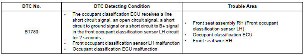
DTC B1780 Front Occupant Classification Sensor LH Circuit Malfunction
DESCRIPTION
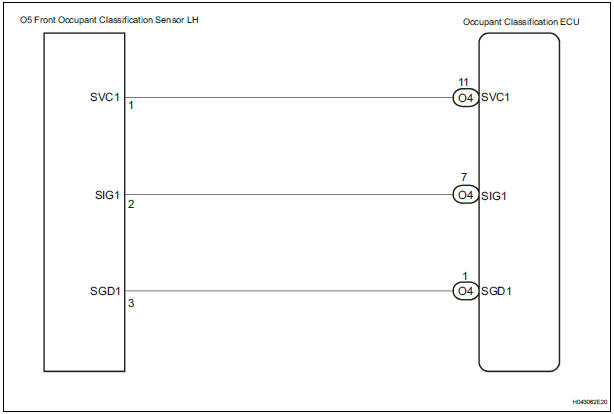
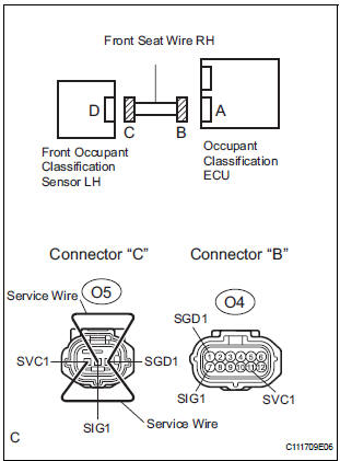
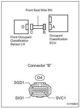
The front occupant classification sensor LH circuit consists of the occupant classification ECU and the front occupant classification sensor LH.
DTC B1780 is recorded when a malfunction is detected in the front occupant classification sensor LH circuit.
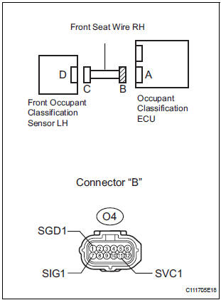
WIRING DIAGRAM
INSPECTION PROCEDURE
HINT:
- If troubleshooting (wire harness inspection) is difficult to perform, remove the front passenger seat installation bolts to see the under surface of the seat cushion.
- In the above case, hold the seat so that it does not fall down. Holding the seat for a long period of time may cause a problem, such as seat rail deformation. Hold the seat only as necessary.
1 CHECK DTC
- Turn the ignition switch to the ON position.
- Clear the DTCs stored in the memory.
HINT: First clear DTCs stored in the occupant classification ECU and then in the center airbag sensor assembly.
- Turn the ignition switch to the LOCK position.
- Turn the ignition switch to the ON position.
- Check the DTCs.
OK: DTC B1780 is not output.
HINT: Codes other than DTC B1780 may be output at this time, but they are not related to this check.
2 CHECK CONNECTION OF CONNECTORS
- Turn the ignition switch to the LOCK position.
- Disconnect the negative (-) terminal cable from the battery, and wait for at least 90 seconds.
- Check that the connectors are properly connected to the occupant classification ECU and the front occupant classification sensor LH.
OK: The connectors are properly connected.
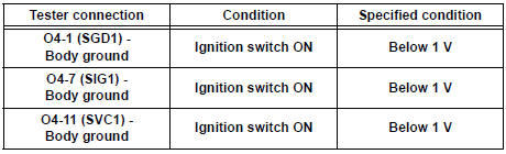
3 CHECK FRONT SEAT WIRE RH (SHORT TO B+)
- Disconnect the connectors from the occupant classification ECU and the front occupant classification sensor LH.
- Connect the negative (-) terminal cable to the battery.
- Turn the ignition switch to the ON position.
- Measure the voltage according to the value(s) in the table below.
Standard voltage
4 CHECK FRONT SEAT WIRE RH (OPEN)
- Turn the ignition switch to the LOCK position.
- Disconnect the negative (-) terminal cable from the battery, and wait for at least 90 seconds.
- Using a service wire, connect O5-1 (SVC1) and O5-3
(SGD1), and connect O5-2 (SIG1) and O5-3 (SGD1) of
connector "C".
NOTICE: Do not forcibly insert a service wire into the terminals of the connector when connecting.
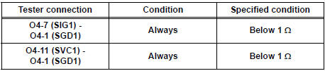
- Measure the resistance according to the value(s) in the table below.
Standard resistance
5 CHECK FRONT SEAT WIRE RH (SHORT)
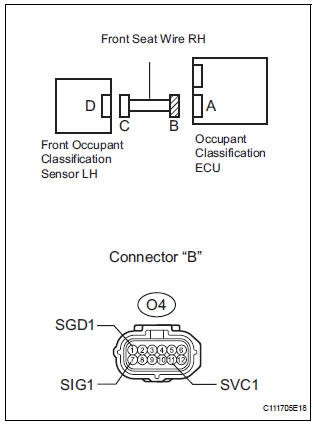
- Disconnect the service wire from connector "C".
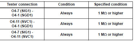
- Measure the resistance according to the value(s) in the table below.
Standard resistance
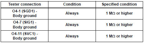
6 CHECK FRONT SEAT WIRE RH (SHORT TO GROUND)
- Measure the resistance according to the value(s) in the table below.
Standard resistance
7 CHECK DTC
- Connect the connectors to the occupant classification ECU and the front occupant classification sensor LH.
- Connect the negative (-) terminal cable to the battery.
- Turn the ignition switch to the ON position.
- Clear the DTCs stored in the memory.
HINT: First clear DTCs stored in the occupant classification ECU and then in the center airbag sensor assembly.
- Turn the ignition switch to the LOCK position.
- Turn the ignition switch to the ON position.
- Check the DTCs.
OK: DTC B1780 is not output.
HINT: Codes other than DTC B1780 may be output at this time, but they are not related to this check.
8 REPLACE OCCUPANT CLASSIFICATION ECU
- Turn the ignition switch to the LOCK position.
- Disconnect the negative (-) terminal cable from the battery, and wait for at least 90 seconds.
- Replace the occupant classification ECU.
HINT: Perform the inspection using parts from a normal vehicle if possible.
9 PERFORM ZERO POINT CALIBRATION
- Connect the negative (-) terminal cable to the battery.
- Connect the intelligent tester to the DLC3.
- Turn the ignition switch to the ON position.
- Using the intelligent tester, perform "Zero point calibration".
OK: "COMPLETED" is displayed.
10 PERFORM SENSITIVITY CHECK
- Using the intelligent tester, perform "Sensitivity check".
Standard value: 27 to 33 kg (59.52 to 72.75 lb)
11 CHECK DTC
- Turn the ignition switch to the ON position.
- Clear the DTCs stored in the memory.
HINT: First clear DTCs stored in the occupant classification ECU and then in the center airbag sensor assembly.
- Turn the ignition switch to the LOCK position.
- Turn the ignition switch to the ON position.
- Check the DTCs.
OK: DTC B1780 is not output.
HINT: Codes other than DTC B1780 may be output at this time, but they are not related to this check.
12 REPLACE FRONT SEAT ASSEMBLY RH
- Turn the ignition switch to the LOCK position.
- Disconnect the negative (-) terminal cable from the battery, and wait for at least 90 seconds.
- Replace the front seat assembly RH.
13 PERFORM ZERO POINT CALIBRATION
- Connect the negative (-) terminal cable to the battery.
- Connect the intelligent tester to the DLC3.
- Turn the ignition switch to the ON position.
- Using the intelligent tester, perform "Zero point calibration".
OK: "COMPLETED" is displayed.
14 PERFORM SENSITIVITY CHECK
- Using the intelligent tester, perform "Sensitivity check".
Standard value: 27 to 33 kg (59.52 to 72.75 lb)
END
 Passenger Side Buckle Switch Circuit Malfunction
DTC B1771 Passenger Side Buckle Switch Circuit Malfunction
DESCRIPTION
The passenger side buckle switch circuit consists of the occupant
classification ECU and the front seat
inner belt assembly ...
 Front Occupant Classification Sensor RH Circuit
Malfunction
Front Occupant Classification Sensor RH Circuit
Malfunction
DTC B1781 Front Occupant Classification Sensor RH Circuit
Malfunction
DESCRIPTION
The front occupant classification sensor RH circuit consists of the occupant
classification ECU and the
front oc ...
Other materials:
On-vehicle inspection
1. INSPECT FRONT AXLE HUB BEARING BACKLASH
(a) Using a dial gauge, check for backlash near the
center of the axle hub.
Maximum:
0.05 mm (0.0020 in.)
If backlash exceeds the maximum, replace the
bearing.
NOTICE:
Ensure that the dial gauge is set at right angles
to the measurement surface ...
Short to GND in Driver Side Squib 2nd Step Circuit
DTC B1182/19 Short to GND in Driver Side Squib 2nd Step Circuit
DESCRIPTION
The driver side squib 2nd step circuit consists of the center airbag sensor
assembly, the spiral cable and
the steering pad.
The circuit instructs the SRS to deploy when deployment conditions are met.
DTC B1182/19 ...
No Answer-Back (Hazard Warning Light and Wireless Door Lock
Buzzer)
DESCRIPTION
If there is no answer-back of the hazard light signal and the wireless door lock
buzzer although the
wireless control function is operating normally, there might be a malfunction in
the hazard light signal and
the wireless door lock buzzer signal which are output from the multiple ...
