Toyota Sienna Service Manual: Front wheel alignment
Adjustment
NOTICE: For vehicles equipped with VSC, if wheel alignment has been adjusted, and if suspension or underbody components have been removed/installed or replaced, be sure to perform the following initialization procedure in order for the system to function normally: 1. Disconnect the negative battery terminal for more than 2 seconds.
2. Reconnect the negative battery terminal.
3. Perform zero point calibration of the yaw rate and acceleration sensor and test mode inspection.
HINT: (See page BC-70)
1. INSPECT TIRE
HINT: (See page TW-2)
2. MEASURE VEHICLE HEIGHT
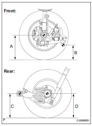
(a) Bounce the vehicle at the corners up and down to stabilize the suspension and inspect the vehicle height.
Vehicle height:
FF 
4WD 
Measuring points: A: Ground clearance of front wheel center
B: Ground clearance of lower suspension arm No. 2 set bolt center
C: Ground clearance of rear axle carrier bushing set bolt center
D: Ground clearance of rear wheel center
NOTICE: Before inspecting the wheel alignment, adjust the vehicle height to the specified value.
HINT: If the vehicle height is not as specified, adjust it by pushing down or lifting the body.
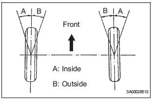
3. INSPECT TOE-IN
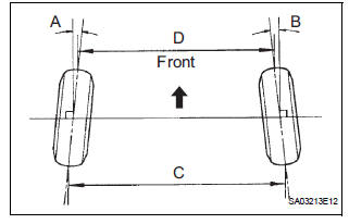
(a) Inspect the toe-in.
Toe-in
FF
4WD
HINT: If the toe-in is not within the specified value, adjust it at the rack ends.
4. ADJUST TOE-IN
(a) Remove the rack boot set clips.
(b) Loosen the tie rod end lock nuts.
(c) Turn the right and left rack ends by an equal amount to adjust the toe-in.
HINT: Adjust the toe-in to the center of the specified value as much as possible.
(d) Make sure that the lengths of the right and left rack ends are the same.
(e) Tighten the tie rod end lock nuts.
Torque: 74 N*m (755 kgf*cm, 55 ft.*lbf) (f) Place the boots on the seats and install the clips.
HINT: Make sure that the boots are not twisted.
5. INSPECT WHEEL ANGLE
(a) Turn the steering wheel fully and measure the turning angle.
Wheel turning angle:
FF 
4WD 
HINT: If the right and left inside wheel angles are not as specified, check the right and left rack end lengths.
6. INSPECT CAMBER, CASTER AND STEERING AXIS INCLINATION
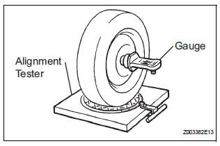
(a) Install the camber-caster-kingpin gauge or position the vehicle on the wheel alignment tester.
(b) Inspect the camber, caster and steering axis inclination.
FF 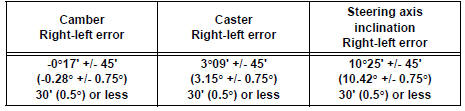
4WD 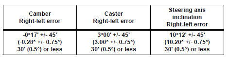
HINT: If the caster and steering axis inclination are not within the specified values, after the camber has been correctly adjusted, recheck the suspension parts for damaged and worn out parts.
7. ADJUST CAMBER
NOTICE: After the camber has been adjusted, inspect the toein.
(a) Remove the front wheel.
(b) Remove the 2 nuts on the lower side of the shock absorber. (Procedure "B")
NOTICE: When removing the nut, hold the bolt not to rotate.
(c) Clean the installation surfaces of the shock absorber and the steering knuckle.
(d) Temporarily install the 2 nuts.
(e) Adjust the camber by pushing or pulling the lower side of the shock absorber in the direction in which the camber adjustment is required.
(f) Tighten the nuts.
Torque: 210 N*m (2140 kgf*cm, 155 ft.*lbf)
NOTICE: When installing the nut, stop the bolt from rotating and tighten the nut.
(g) Install the front wheel.
Torque: 103 N*m (1050 kgf*cm, 76 ft.*lbf) (h) Check the camber.
HINT:
- Adjust the camber to the center of the specified value as much as possible.
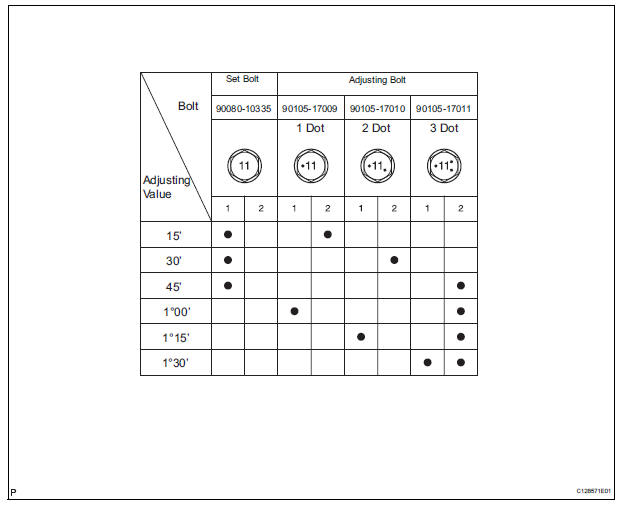
- Adjusting value for the set bolts is 6' to 30' (0.1° to 0.5°).
- If the camber is not within the specified value, using the following table, estimate how much additional camber adjustment will be required, and select the camber adjusting bolt.
NOTICE: Tighten the adjusting bolt with a washer and a new nut.
(i) Perform the procedure mentioned above again. At procedure "B", replace 1 or 2 selected bolts.
HINT: Replace one bolt at a time when replacing 2 bolts.
 Suspension system
How to proceed with troubleshooting
HINT:
This is the repair procedure for vehicle pull.
Problem symptoms table
FRONT SUSPENSION SYSTEM
REAR SUSPENSION SYSTEM
...
 Rear wheel alignment
ADJUSTMENT
NOTICE:
For vehicles equipped with VSC, if wheel alignment has
been adjusted, and if suspension or underbody
components have been removed/installed or replaced, be
sure to perform the ...
Other materials:
On-vehicle inspection
1. INSPECT CAMSHAFT TIMING CONTROL VALVE ASSEMBLY
Connect the intelligent tester to the DLC3.
Turn the ignition switch to the ON position.
Start the engine and warm it up.
Select the intelligent tester from the ACTIVE TEST
menu.
Check the engine speed ...
Indicator Circuit
DESCRIPTION
The indicator displays the location of the obstacle and the approximate
distance between the vehicle and
the obstacle either by blinking or turning on.
WIRING DIAGRAM
INSPECTION PROCEDURE
1 CHECK HARNESS AND CONNECTOR (CLEARANCE WARNING ECU - AIR CONDITIONER
AMPLIFIER)
...
Compressor and magnetic clutch
COMPONENTS
...
