Toyota Sienna Service Manual: Short in Front Pretensioner Squib RH Circuit
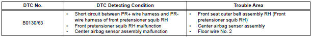
DTC B0130/63 Short in Front Pretensioner Squib RH Circuit
DESCRIPTION
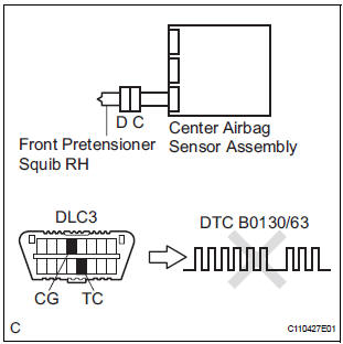
The front pretensioner squib RH circuit consists of the center airbag sensor assembly and the front seat outer belt assembly RH.
This circuit instructs the SRS to deploy when deployment conditions are met.
DTC B0130/63 is recorded when a short circuit is detected in the front pretensioner squib RH circuit.
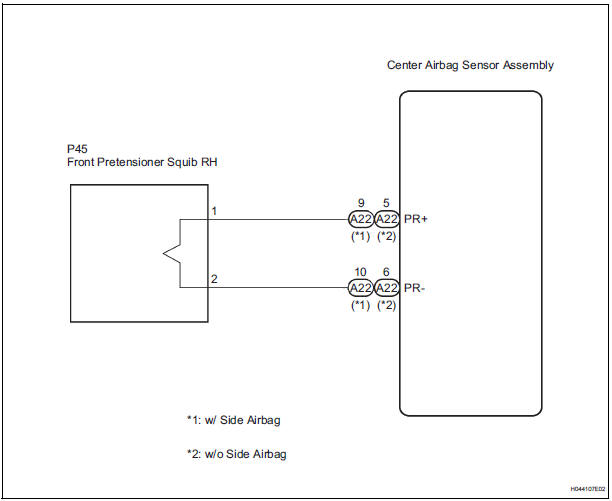
WIRING DIAGRAM
INSPECTION PROCEDURE
HINT:
- Perform the simulation method by selecting the "check mode" (signal check) with the intelligent tester
- After selecting the "check mode" (signal check), perform the simulation method by wiggling each connector of the airbag system or driving the vehicle on a city or rough road
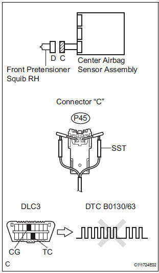
1 CHECK FRONT SEAT OUTER BELT ASSEMBLY RH (FRONT PRETENSIONER SQUIB RH)
- Turn the ignition switch to the LOCK position.
- Disconnect the negative (-) terminal cable from the battery, and wait for at least 90 seconds.
- Disconnect the connectors from the front seat outer belt assembly RH.
- Connect the white wire side of SST (resistance 2.1 Ω) to the floor wire No. 2.
CAUTION: Never connect a tester to the front seat outer belt assembly RH (front pretensioner squib RH) for measurement, as this may lead to a serious injury due to airbag deployment.
NOTICE: Do not forcibly insert the SST into the terminals of the connector when connecting.
Insert the SST straight into the terminals of the connector.
SST 09843-18060
- Connect the negative (-) terminal cable to the battery, and wait for at least 2 seconds.
- Turn the ignition switch to the ON position, and wait for at least 60 seconds.
- Clear the DTCs stored in memory.
- Turn the ignition switch to the LOCK position.
- Turn the ignition switch to the ON position, and wait for at least 60 seconds.
- Check the DTCs.
OK: DTC B0130/63 is not output.
HINT: Codes other than DTC B0130/63 may be output at this time, but they are not related to this check.
REPLACE FRONT SEAT OUTER BELT ASSEMBLY RH
2 CHECK CONNECTORS
- Turn the ignition switch to the LOCK position.
- Disconnect the negative (-) terminal cable from the battery, and wait for at least 90 seconds.
- Disconnect the SST (resistance 2.1 Ω) from the floor wire No. 2.
- Check that the floor wire No. 2 connectors (on the front seat outer belt assembly RH side) are not damaged.
OK: The lock button is not disengaged, and the claw of the lock is not deformed or damaged.
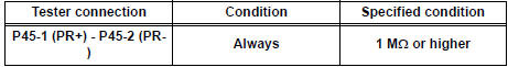
3 CHECK FLOOR WIRE NO.2 (FRONT PRETENSIONER SQUIB RH CIRCUIT)
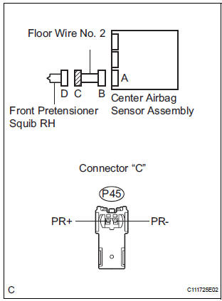
- Disconnect the connector from the center airbag sensor assembly.
- Release the activation prevention mechanism built into connector "B".
- Measure the resistance according to the value(s) in the table below.
Standard resistance
4 CHECK CENTER AIRBAG SENSOR ASSEMBLY
- Connect the connectors to the front seat outer belt assembly RH and the center airbag sensor assembly.
- Connect the negative (-) terminal cable to the battery, and wait for at least 2 seconds.
- Turn the ignition switch to the ON position, and wait for at least 60 seconds.
- Clear the DTCs stored in memory.
- Turn the ignition switch to the LOCK position.
- Turn the ignition switch to the ON position, and wait for at least 60 seconds.
- Check the DTCs.
OK: DTC B0130/63 is not output.
HINT: Codes other than code B0130/63 may be output at this time, but they are not related to this check.
USE SIMULATION METHOD TO CHECK
 Seat Belt Buckle Switch LH Circuit Malfunction
DTC B0126/27 Seat Belt Buckle Switch LH Circuit Malfunction
DESCRIPTION
The seat belt buckle switch LH circuit consists of the center airbag sensor
assembly and the front seat
inner belt assembly ...
 Open in Front Pretensioner Squib RH Circuit
DTC B0131/64 Open in Front Pretensioner Squib RH Circuit
DESCRIPTION
The front pretensioner squib RH circuit consists of the center airbag sensor
assembly and the front seat
outer belt assembly R ...
Other materials:
Removal
NOTICE:
When installing, coat the parts indicated by the arrows
with power steering fluid or molybdenum disulfide
lithium base grease (See page PS-21).
1. INSPECT CENTER FRONT WHEEL
2. REMOVE FRONT WHEEL
3. SEPARATE TIE ROD ASSEMBLY LH
SST 09628-62011
4. SEPARATE TIE ROD ASSEMBLY RH
SST 096 ...
Before driving
Floor mat
Use only floor mats designed specifically for vehicles of the same
model and model year as your vehicle. Fix them securely in place
onto the carpet.
Insert the retaining hooks (clips)
into the floor mat eyelets.
Turn the upper knob of each
retaining hook (clip) to secu ...
Customer problem analysis
HINT:
In troubleshooting, confirm that the problem symptoms
have been accurately identified. Preconceptions should be
discarded in order to make an accurate judgment. To
clearly understand what the problem symptoms are, it is
extremely important to ask the customer about the
problem an ...
