Toyota Sienna Service Manual: Rear wheel alignment
ADJUSTMENT
NOTICE: For vehicles equipped with VSC, if wheel alignment has been adjusted, and if suspension or underbody components have been removed/installed or replaced, be sure to perform the following initialization procedure in order for the system to function normally: 1. Disconnect the negative battery terminal for more than 2 seconds.
2. Reconnect the negative battery terminal.
3. Perform zero point calibration of the yaw rate and acceleration sensor and test mode inspection.
HINT: (See page BC-70)
1. INSPECT TIRE
HINT: (See page TW-2)
2. MEASURE VEHICLE HEIGHT
NOTICE: Before inspecting the wheel alignment, adjust the vehicle height to the specified valve.
3. INSPECT TOE-IN
(a) Inspect the toe-in.
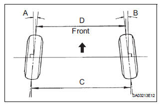
Toe-in
FF 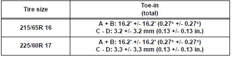
4WD 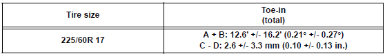
HINT: If the toe-in is not within the specified value, inspect the suspension parts and replace them if necessary.
4. INSPECT CAMBER
(a) Install the camber-caster-kingpin gauge or position the vehicle on the wheel alignment tester.
(b) Inspect the camber.
Camber
FF 
4WD 
HINT: If the measured value is not within the specified value, inspect the suspension parts for damage and the wear and replace them if necessary because camber is not adjustable.
 Front wheel alignment
Adjustment
NOTICE:
For vehicles equipped with VSC, if wheel alignment has
been adjusted, and if suspension or underbody
components have been removed/installed or replaced, be
sure to perform the ...
 Front shock absorber with coil spring
COMPONENTS
...
Other materials:
Wrong Disc/ Disc cannot be Read/ Wrong Disc/ Disc cannot be Read
DTC 62-41 Wrong Disc
DTC 62-42 Disc cannot be Read
DTC 63-41 Wrong Disc
DTC 63-42 Disc cannot be Read
DESCRIPTION
DTC No.
DTC Detecting Condition
Trouble Area
62-41
An unsuitable disc is inserted
CD
Radio receiver
62-42
Th ...
Sound Signal Circuit between Radio and Navigation Assembly and
Stereo Component Amplifier
DESCRIPTION
The radio and navigation assembly sends a sound signal to the stereo
component amplifier through this
circuit.
The sound signal that has been sent is amplified by the stereo component
amplifier, and then is sent to
the speakers.
If there is an open or short in the circuit, s ...
Installation
HINT:
Use the same procedures for the RH side and LH side.
The procedures listed below are for the LH side.
1. INSTALL REAR AIRBAG SENSOR LH
Check that the ignition switch is off.
Check that the battery negative (-) terminal is
disconnected.
CAUTION:
...
