Toyota Sienna Service Manual: No Signal from Transmitter ID1
DESCRIPTION
The tire pressure warning valve and transmitters that are installed in the tire and wheel assemblies measure the air pressure of the tires. The measured values are transmitted to the tire pressure warning antenna and receiver on the body as radio waves and then sent to the tire pressure warning ECU. The ECU compares the measured air pressure values with the air pressure threshold. When the measured air pressure value is less than this threshold, the warning light in the combination meter comes on.
The tire pressure warning valve and transmitters constantly send radio waves to the tire pressure warning antenna and receiver.
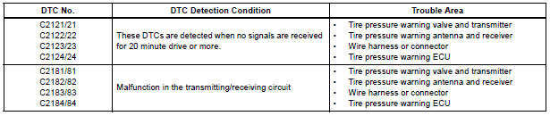
Under the following conditions below, the tire pressure warning antenna and receiver is unable to receive the signals from the tire pressure warning valves and transmitters, and a DTC is stored.
- Facilities or devices that use similar radio frequencies are located in the vicinity of the vehicle.
- Devices using similar radio frequencies are used in the vehicle.
- The goods which obstruct the radio signal of the valve and transmitter, for example, tire chain or window film.
HINT: When no signals are received for 20 minutes or more, a DTC is output.
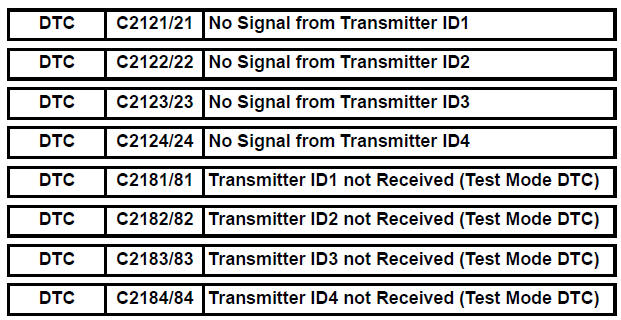
DTCs from C2121/21 to C2124/24 can only be cleared by using the tester. DTCs from C2181/81 to C2184/84 can be cleared when the transmitter in the tire pressure warning valve and transmitter sends a forced transmission signal or test mode ends. DTCs from C2181/81 to C2184/84 are output only in test mode.
HINT: It is necessary to perform the procedure to identify the tire pressure warning valve and transmitter that is malfunctioning because it cannot be identified by the output DTC.
WIRING DIAGRAM

INSPECTION PROCEDURE
NOTICE:
- When replacing the tire pressure warning ECU, read the IDs stored in the ECU using the intelligent tester and write them down before removal.
- It is necessary to perform initialization (See page TW-23) after registration (See page TW-20) of the transmitter IDs into the tire pressure warning ECU after the ECU and/or valve and transmitter have been replaced.
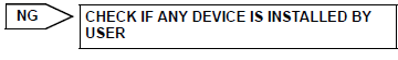
1 CHECK FREQUENCY RECEIVING CONDITION
(a) Check if the vehicle is not located in areas such as described below:
(1) Facilities or devices that use similar radio frequencies are located in the vicinity of the vehicle.
HINT: If the vehicle is located in areas described above, the tire pressure warning light may come on after blinking 1 minute only in a particular area.
(2) Devices using similar radio frequencies are used in the vehicle.
OK: Facilities, or devices that use similar radio frequencies are not located in the vicinity of the vehicle.
HINT: Radio frequency may be interrupted due to surroundings or devices installed by the user.

2 IDENTIFY TRANSMITTER CORRESPONDING TO DTC
(a) Set the tire pressure to the appropriate specified values.
Cold tire inflation pressure 
(b) Make sure that the ignition switch is off.
(c) Connect the intelligent tester to the DLC3.
(d) Turn the ignition switch to the ON position.
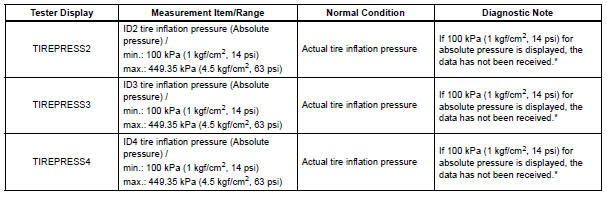
(e) Select "TIREPRESS" by following the prompts displayed on the intelligent tester.
TIRE PRESSURE: 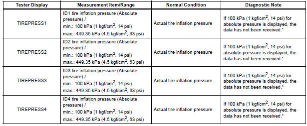
HINT: *: It may take about 5 to 6 minutes until the values are displayed.
(f) Rapidly reduce the tire pressure for each wheel at least 40 kPa (0.41 kg/cm2, 5.8 psi) within 30 seconds.
(g) Check the DATA LIST.
NOTICE:
- It takes about 5 to 6 minutes to display the updated tire pressure data.
- When no "TIREPRESS" data has changed, reset the tire pressure to the appropriate specified value and rotate the tire 90 to 270 degrees. Then rapidly release the tire pressure and recheck it.
- Record the transmitter ID of which "TIREPRESS" data corresponds to each tire.
(h) After confirming that one of "TIREPRESS" data for one tire (ID1 to ID4) has changed, repeat this procedure one by one. Identify the transmitter that corresponds to DTC.
Result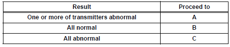
3 CHECK HARNESS AND CONNECTOR (ECU - RECEIVER)
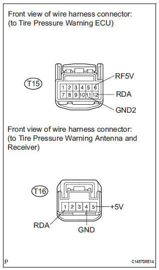
(a) Disconnect the T15 ECU connector.
(b) Disconnect the T16 receiver connector.
(c) Measure the resistance according to the value(s) in the table below.
Standard resistance 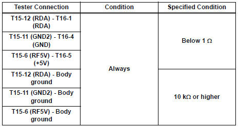

4 INSPECT TIRE PRESSURE WARNING VALVE AND TRANSMITTER
(a) Make sure that the ignition switch is off.
(b) Connect the intelligent tester to the DLC3.
(c) Turn the ignition switch to the ON position.
(d) Select REGIT ID CODE by following the prompts displayed on the intelligent tester.
TIRE PRESSURE: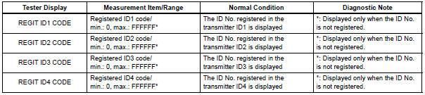
(e) Check the ID number on the identified transmitter by removing it from the tire and wheel.
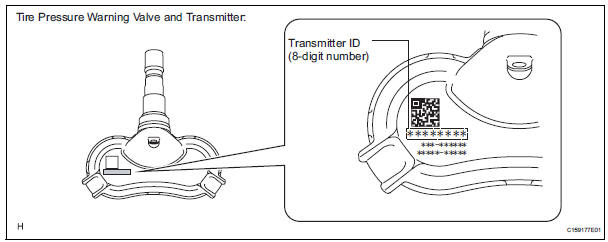
(f) Confirm that the ID number on the transmitter and recorded transmitter ID match.
Result 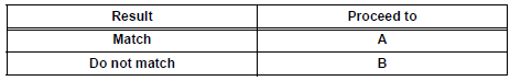

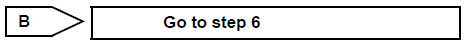
5 REPLACE TIRE PRESSURE WARNING VALVE AND TRANSMITTER
(a) Replace the tire pressure warning valve and transmitter (See page TW-84).

6 REGISTRATION OF TRANSMITTER ID
(a) Perform registration (See page TW-20).

7 PERFORM INITIALIZATION
(a) Perform initialization (See page TW-23).
8 READ VALUE ON DATA LIST
(a) Make sure that the ignition switch is off.
(b) Connect the intelligent tester to the DLC3.
(c) Turn the ignition switch to the ON position.
(d) Select "TIREPRESS" by following the prompts displayed on the intelligent tester.
TIRE PRESSURE: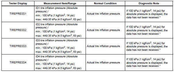
HINT: *: It may take about 5 to 6 minutes until the values are displayed.
Result 

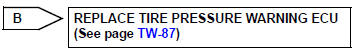
9 REPLACE TIRE PRESSURE WARNING ANTENNA AND RECEIVER
(a) Replace the tire pressure warning antenna and receiver (See page TW-81).

10 READ VALUE ON DATA LIST
(a) Make sure that the ignition switch is off.
(b) Connect the intelligent tester to the DLC3.
(c) Turn the ignition switch to the ON position.
(d) Select "TIREPRESS" by following the prompts displayed on the intelligent tester.
TIRE PRESSURE: 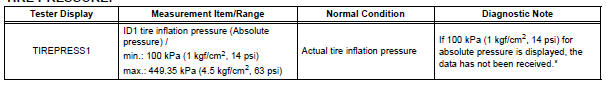
HINT: *: It may take about 5 to 6 minutes until the values are displayed.
Result 

END
 Transmitter ID1 Operation Stop
DESCRIPTION
The tire pressure warning valve and transmitters that are installed in the
tire and wheel assemblies
measure the air pressures of the tires. The measured values are transmitted to ...
 Transmitter ID1 Error
DESCRIPTION
The tire pressure warning valve and transmitters that are installed in the
tire and wheel assemblies
measure the air pressure of the tires. The measured values are transmitted to
...
Other materials:
Power window regulator
motor
INSPECTION
1. INSPECT POWER WINDOW REGULATOR MOTOR
(FRONT RH)
Remove the power window regulator motor.
Apply battery voltage to the motor connector
according to the table below.
NOTICE:
Do not apply battery to any terminals except
terminals 1 and 2.
Standard
2. INS ...
Eject Error/ Elevator Error/ Clamp Error
DTC 63-45 Eject Error
DTC 63-51 Elevator Error
DTC 63-52 Clamp Error
DESCRIPTION
DTC No.
DTC Detection Condition
Trouble Area
63-45
Magazine cannot be ejected.
Radio and navigation assembly
63-51
Mechanical error occurs during elevator ...
Reassembly
1. INSTALL BACK DOOR STOPPER LOWER
Install the 2 stoppers with the 4 bolts.
Torque: 7.0 N*m (71 kgf*cm, 62 in.*lbf)
2. INSTALL BACK DOOR BASE STOPPER BRACKET
Install the 2 brackets with the 4 bolts.
Torque: 7.0 N*m (71 kgf*cm, 62 in.*lbf)
3. INSTALL BACK DOOR WITH MOTOR LOCK ASSEMB ...
