Toyota Sienna Service Manual: Headlight dimmer switch
COMPONENTS
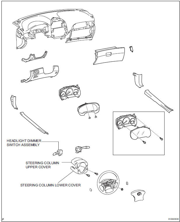
REMOVAL
1. REMOVE STEERING COLUMN LOWER COVER
2. REMOVE STEERING COLUMN UPPER COVER
3. REMOVE HEADLIGHT DIMMER SWITCH ASSEMBLY
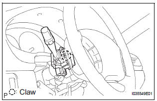
- Disconnect the connector.
- Release the claw fitting and remove the headlight dimmer switch assembly.
INSPECTION
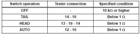
1. HEADLIGHT DIMMER SWITCH ASSEMBLY
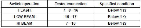
- Inspect light control switch resistance.
- Check that there is resistance between the terminals at each switch position as shown in the chart.
Resistance
- Inspect light control switch resistance.
- Check that there is resistance between the terminals at each switch position as shown in the chart.
Resistance
- Inspect light control switch resistance.
- Check that there is resistance between the terminals at each switch position as shown in the chart.
Resistance
- Inspect light control switch resistance.
- Check that there is resistance between the terminals at each switch position as shown in the chart.
Resistance
INSTALLATION
1. INSTALL HEADLIGHT DIMMER SWITCH ASSEMBLY
2. INSTALL STEERING COLUMN UPPER COVER
3. INSTALL STEERING COLUMN LOWER COVER
 Vanity light
ON-VEHICLE INSPECTION
1. LH VISOR ASSEMBLY
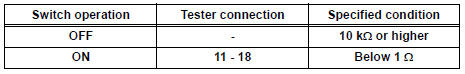
Inspect vanity light resistance.
check that the resistance exists between the
terminal 1 and the terminal 2 when the light is
oper ...
 Turn signal light switch
ON-VEHICLE INSPECTION
1. INSPECT TURN SIGNAL FLASHER CIRCUIT
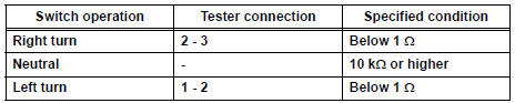
Measure voltage between the terminals as shown in
the chart below.
Voltage
Connect the connector to turn the si ...
Other materials:
Evaporative Emission System Switching Valve Control Circuit High
DTC SUMMARY
DESCRIPTION
The circuit description can be found in the EVAP (Evaporative Emission)
System (See page ES-404).
INSPECTION PROCEDURE
Refer to the EVAP System (See page ES-404).
MONITOR DESCRIPTION
5 hours*1 after the ignition switch is turned off, the electric vacuum pump
...
Transmitter ID not Registered
DTC C2171/71 Transmitter ID not Registered
DESCRIPTION
The IDs of each tire pressure warning valve and transmitters are registered
to the tire pressure warning
ECU.
When the IDs have never been registered, a DTC is output.
INSPECTION PROCEDURE
NOTICE:
When replacing the tire pressu ...
Short to B+ in Front Passenger Side Squib 2nd
Step Circuit
DTC B1188/56 Short to B+ in Front Passenger Side Squib 2nd
Step Circuit
DESCRIPTION
The front passenger side squib 2nd step circuit consists of the center airbag
sensor assembly and the
front passenger airbag assembly.
The circuit instructs the SRS to deploy when deployment conditions are m ...
