Toyota Sienna Service Manual: How to proceed with troubleshooting
HINT: The intelligent tester can be used in steps 2, 3, 4, 6 and 9.
1 VEHICLE BROUGHT TO WORKSHOP
2 CONNECT INTELLIGENT TESTER TO DLC3
HINT: If the display indicates a communication fault in the tester, inspect the DLC3.
3 CHECK DTC AND FREEZE FRAME DATA
- Check for DTC(s) and freeze frame data.
HINT: Record or print the DTCs and freeze frame data, if necessary.
4 CLEAR DTC AND FREEZE FRAME DATA
- Clear the DTC(s) and freeze frame data
5 CONDUCT VISUAL INSPECTION
6 SET CHECK MODE DIAGNOSIS
- Set the check mode
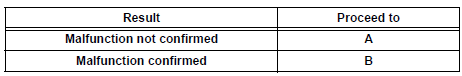
7 CONFIRM PROBLEM SYMPTOMS
HINT: If the engine does not start, perform steps 9 and 11 first.
Result
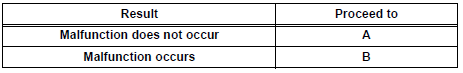
8 SIMULATE SYMPTOMS
9 CHECK FOR DTCS
- Check for DTCs.
Result
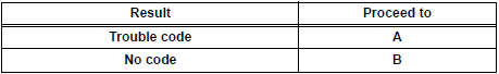
10 REFER TO DTC CHART
HINT: Refer to the DTC chart
GO TO STEP 13
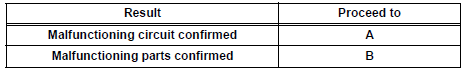
11 CONDUCT BASIC INSPECTION
HINT: Refer to "BASIC INSPECTION".
Result
12 REFER TO PROBLEM SYMPTOMS TABLE
HINT: Refer to "PROBLEM SYMPTOMS TABLE".
Result
13 CHECK ECM POWER SOURCE CIRCUIT
HINT: Refer to "ECM POWER SOURCE CIRCUIT"
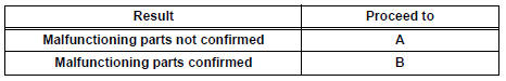
14 CONDUCT CIRCUIT INSPECTION
Result
15 CHECK FOR INTERMITTENT PROBLEMS
HINT: Refer to "CHECK FOR INTERMITTENT PROBLEMS"
GO TO STEP 17
16 CONDUCT PARTS INSPECTION
17 IDENTIFY PROBLEM
18 ADJUST AND/OR REPAIR
19 CONDUCT CONFIRMATION TEST
END
 Definition of terms
Terms
Definitions
Monitor Description
Description of what ECM monitors and how to detect malfunctions
(monitoring purpose and details).
Related DTCs
A gro ...
 Check for intermittent
problems
Check for intermittent
problems
1. CHECK FOR INTERMITTENT PROBLEMS
HINT:
For use of the intelligent tester only:
Inspect the vehicle's ECM using check mode.
Intermittent problems are easier to detect with an
intelligent teste ...
Other materials:
Display Signal Circuit between Video Terminal and Television Display
DESCRIPTION
This is the display signal circuit from the video terminal to the television
display assembly.
WIRING DIAGRAM
INSPECTION PROCEDURE
1 CHECK HARNESS AND CONNECTOR (TELEVISION DISPLAY ASSEMBLY - VIDEO
TERMINAL)
Disconnect the connectors from the video terminal and
tele ...
Canceling the power sliding door system (vehicles with power
sliding doors)
Turn the main switch off to disable
the power sliding door system.
Off
The sliding doors can only be
opened and closed manually.
On*
The power sliding door can be
opened and closed with the power
sliding door switches for the front
occupants or wireless remote control
even if ...
Push Switch / Key Unlock Warning Switch Malfunction
DTC B2780 Push Switch / Key Unlock Warning Switch Malfunction
DESCRIPTION
This DTC will be output if the transponder key ECU does not detect that the
unlock warning switch is on
even when the ignition switch is on (Under the normal conditions, the unlock
warning switch is on when
the ignitio ...
