Toyota Sienna Service Manual: How to proceed with troubleshooting
HINT: *: Use the intelligent tester.
1 VEHICLE BROUGHT TO WORKSHOP
2 CUSTOMER PROBLEM ANALYSIS
- Confirm problem symptoms
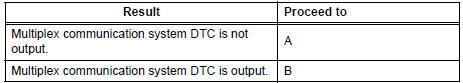
3 CHECK MULTIPLEX COMMUNICATION SYSTEM*
- Check if the multiplex communication system DTC is output.
HINT: The center airbag sensor assembly of this system is connected to the multiplex communication system.
Therefore, before starting troubleshooting, make sure to check that there is no trouble in the multiplex communication system.
Result:
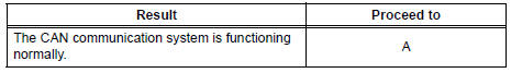
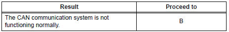
4 CHECK CAN COMMUNICATION SYSTEM
- Use the intelligent tester to check if the CAN communication system is functioning normally .
HINT: The ECM is connected to the CAN communication system. Therefore, before starting troubleshooting, make sure to check that there is no trouble in the CAN communication system.
Result:
5 SRS WARNING LIGHT CHECK
- Proceed to Diagnosis System
6 CHECK FOR DTC*
- Proceed to DTC Check / Clear.
Result:
7 DIAGNOSTIC TROUBLE CODE CHART
- Proceed to Diagnostic Trouble Code Chart
8 SYMPTOM SIMULATION
- Proceed to Diagnosis System
9 PROBLEM SYMPTOMS TABLE
- Proceed to Problem Symptoms Table
10 CIRCUIT INSPECTION*
11 IDENTIFICATION OF PROBLEM
12 REPAIR OR REPLACEMENT
13 CONFIRMATION TEST
END
 System description
1. GENERAL
In conjunction with impact absorbing structure for a
frontal collision, the SRS (Supplemental Restraint
System) driver airbag and front passenger airbag
were designed to sup ...
 Problem symptoms table
HINT:
Proceed to the troubleshooting for each circuit in the table
below.
AIRBAG SYSTEM
Symptom
Suspected Area
The SRS warning light goes off after the primary
check, ...
Other materials:
Removal
1. REMOVE FRONT WHEELS
2. REMOVE ENGINE UNDER COVER NO.1
3. DRAIN AUTOMATIC TRANSAXLE FLUID
(a) Remove the drain plug, gasket and drain ATF.
(b) Install a new gasket and the drain plug.
Torque: 49 N*m (500 kgf*cm, 36 ft.*lbf)
4. REMOVE FRONT DRIVE SHAFT ASSEMBLY LH
HINT:
(See page DS-6)
...
Mass or Volume Air Flow Circuit Range / Performance
Problem
DTC P0101 Mass or Volume Air Flow Circuit Range / Performance
Problem
DESCRIPTION
Refer to DTC P0100
DTC No.
DTC Detection Condition
Trouble Area
P0101
High voltage:
Conditions (a), (b) and (c) continue for more than
10 seconds (2 trip de ...
Short to B+ in Front Pretensioner Squib RH Circuit
DTC B0133/62 Short to B+ in Front Pretensioner Squib RH Circuit
DESCRIPTION
The front pretensioner squib RH circuit consists of the center airbag sensor
assembly and the front seat
outer belt assembly RH.
This circuit instructs the SRS to deploy when deployment conditions are met.
DTC B01 ...
