Toyota Sienna Service Manual: Ignition Switch Circuit
DESCRIPTION
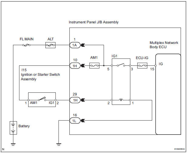
When the ignition switch is turned to the ON position, battery positive voltage is applied to terminal IG of the ECU. When battery positive voltage is applied to terminal IG of the ECU while the theft deterrent system is operating, the warning stops.
WIRING DIAGRAM
INSPECTION PROCEDURE
1 INSPECT FUSES (ECU-IG, AM1)
- Remove the ECU-IG and AM1 fuses from the instrument panel J/B.
- Measure the resistance.
Standard resistance: Below 1 Ω
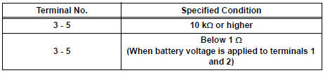
2 INSPECT RELAY (IG1)
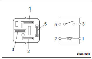
- Remove the IG1 relay from the instrument panel J/B.
- Check the operation of the IG1 relay.
Standard resistance
3 INSPECT IGNITION OR STARTER SWITCH ASSEMBLY
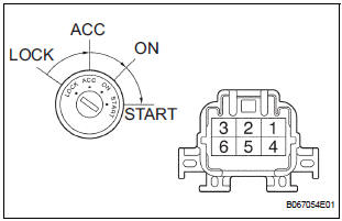
- Disconnect the I15 switch connector.
- Measure the resistance according to the value(s) in the table below.
Standard resistance

4 CHECK INSTRUMENT PANEL JUNCTION BLOCK ASSEMBLY (POWER SOURCE)
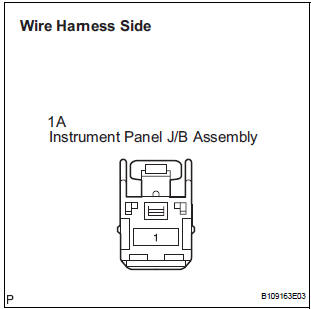
- Disconnect the 1A J/B connector.
- Turn the ignition switch ON.
- Measure the voltage according to the value(s) in the table below.
Standard voltage
REPLACE INSTRUMENT PANEL J/B ASSEMBLY
 Security Horn Circuit
DESCRIPTION
During the alarm sounding state, the relay in the ECU turns on and off in a
cycle of approximately 0.2
seconds, causing the security horn to sound.
WIRING DIAGRAM
INSPECTION PROC ...
 Security Indicator Light Circuit
DESCRIPTION
Even when the theft deterrent system is in the disarmed state, the security
indicator blinks due to a signal
output from the immobiliser system. The security indicator blinks continuou ...
Other materials:
Window lock switch
Press the switch down to lock the
passenger window switches.
Use this switch to prevent children
from accidentally opening or closing
a passenger window.
The power windows can be operated when
The engine switch is in the “ON” position (vehicles without a smart key
system)
or IGNIT ...
Center Airbag Sensor Assembly Communication
Circuit Malfunction
DTC B1790 Center Airbag Sensor Assembly Communication
Circuit Malfunction
DESCRIPTION
The center airbag sensor assembly communication circuit consists of the
occupant classification ECU and
the center airbag sensor assembly.
DTC B1790 is recorded when a malfunction is detected in the center ...
Reassembly
1. INSTALL FRONT AXLE HUB LH BEARING
(a) Using SST(s) and a press, install a new front axle
hub LH bearing to the steering knuckle LH.
SST 09950-60020 (09951-00810), 09950-70010
(09951-07100)
2. INSTALL DISC BRAKE DUST COVER FRONT LH
(a) Place the disc brake dust cover front LH and using ...
