Toyota Sienna Service Manual: Ignition Switch Circuit
DESCRIPTION
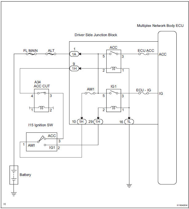
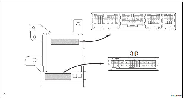
The Multiplex network body ECU receives the ACC and IG signals from the ignition switch.
WIRING DIAGRAM
INSPECTION PROCEDURE
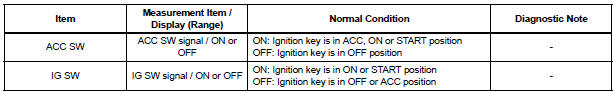
1 READ VALUE OF INTELLIGENT TESTER
- Connect the intelligent tester to DLC3.
- Turn the ignition switch ON and push the intelligent tester main switch ON.
- Select the items below in the DATA LIST, and read the displays on the intelligent tester.
BODY NO.1:
2 INSPECT FUSE
- Inspect the ECU ACC fuse, ECU-IG fuse and AM1 fuse in instrument panel junction block assembly.
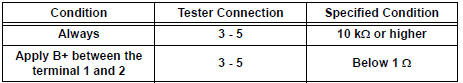
3 INSPECT RELAY
- Inspect ACC relay continuity.
Resistance
- Inspect IG1 relay continuity.
Resistance
4 INSPECT INSTRUMENT PANEL JUNCTION BLOCK ASSEMBLY (ACC, IG)
- Measure the voltage between the terminals as shown in the chart below.
Voltage

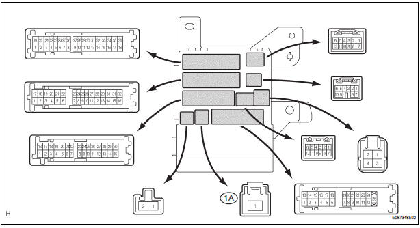
5 INSPECT INSTRUMENT PANEL JUNCTION BLOCK ASSEMBLY (+B)
- Measure voltage between the terminal 1A-1 of the instrument panel junction block assembly and body ground.
Voltage

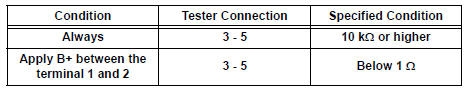
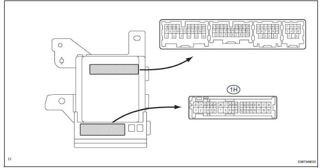
6 INSPECT INSTRUMENT PANEL JUNCTION BLOCK ASSEMBLY
- Measure voltage between the terminal 1H-10 of the instrument panel junction block assembly and body ground.
Voltage

REPAIR OR REPLACE HARNESS OR CONNECTOR
 Light Sensor Circuit Malfunction
DTC B1244 Light Sensor Circuit Malfunction
DESCRIPTION
This DTC is output when failure in the light sensor circuit is detected.
DTC No.
DTC Detection Condition
Trouble Area ...
 Headlight Relay Circuit
DESCRIPTION
The Multiplex network body ECU controls HEAD relay when signal is received
from headlight dimmer
switch assembly.
WIRING DIAGRAM
INSPECTION PROCEDURE
1 PERFORM ACTIVE TEST BY IN ...
Other materials:
Rear Air Outlet Damper Position Sensor Circuit
DESCRIPTION
This sensor detects the position of the rear air outlet control servo motor
and sends the appropriate
signals to the A/C amplifier. The position sensor is built in the rear air
outlet control servo motor.
The position sensor's resistance changes as the rear air outlet contro ...
Stowing the third seats (power seats)
You can operate the power third seats when the shift lever is in P.
Before stowing or returning third seat, remove any items from the floor
area to prevent interference with moving parts.
Before stowing the third seats
Lower the center head
restraint to the lowest position and stow th ...
Wrong Disc/ Disc cannot be Read
DTC 44-41 Wrong Disc
DTC 44-42 Disc cannot be Read
DESCRIPTION
DTC No.
DTC Detecting Condition
Trouble Area
44-41
An unsuitable disc is inserted
DVD
Television display assembly
44-42
The disc cannot be read.
IN ...
