Toyota Sienna Service Manual: Inspection
1. INSPECT VANE PUMP SHAFT AND BUSHING IN VANE PUMP FRONT HOUSING
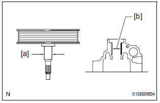
(a) Using a micrometer, measure the outer diameter [a] of the vane pump shaft with pulley.
(b) Using vernier calipers, measure the inner diameter [b] of the vane pump front housing bushing.
(c) Calculate the oil clearance.
Oil clearance = Inner diameter of the bushing [b] - Outer diameter of the shaft [a]
Maximum oil clearance: 0.07 mm (0.0028 in.)
If the oil clearance exceeds the maximum, replace the vane pump assembly.
2. INSPECT VANE PUMP ROTOR AND VANE PUMP PLATE CLEARANCE
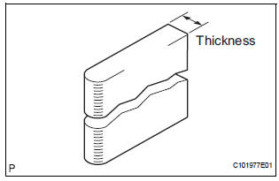
(a) Using a micrometer, measure the thickness of the vane pump plates.
Standard thickness: 1.405 to 1.411 mm (0.05531 to 0.05555 in.) If the thickness is not within the specified range, replace the vane pump assembly.
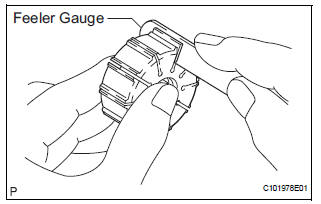
(b) Using a feeler gauge, measure the clearance between the side face of the vane pump rotor groove and the vane pump plates.
Maximum clearance: 0.03 mm (0.0012 in.) If the clearance exceeds the maximum, replace the vane pump assembly.
3. INSPECT FLOW CONTROL VALVE ASSEMBLY
(a) Coat the flow control valve assembly with power steering fluid and check that it falls smoothly into the flow control valve due to its own weight.
If the control valve does not fall into the hole smoothly, replace the vane pump assembly.
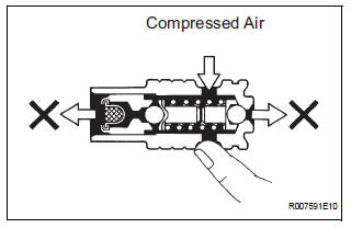
(b) Check the flow control valve assembly for leaks.
Close one of the holes and apply compressed air, 392 to 490 kPa (4 to 5 kgf/cm2, 57 to 71 psi), into the opposite side hole, and confirm that air does not come out from the holes in the ends of the flow control valve assembly.
If air leaks, replace the vane pump assembly.
4. INSPECT FLOW CONTROL VALVE COMPRESSION SPRING
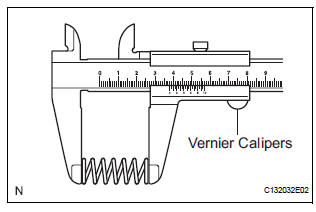
(a) Using vernier calipers, measure the free length of the flow control valve compression spring.
Minimum free length: 29.2 mm (1.150 in.) If the length is less than the minimum, replace the vane pump assembly
5. INSPECT PRESSURE PORT UNION
If the union seat in the pressure port union is severely damaged, replace the vane pump assembly.
6. INSPECT TOTAL PRELOAD
(a) Check that the pump rotates smoothly without abnormal noise.
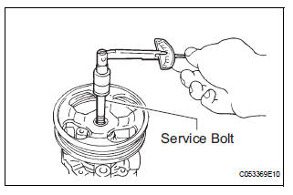
(b) Temporarily install the service bolt.
Recommended service bolt: Thread diameter: 10 mm (0.39 in.) Thread pitch: 1.25 mm (0.0492 in.) Bolt length: 50 mm (1.97 in.)
(c) Using a torque wrench, check the pump rotating torque.
Rotating torque: 0.27 N*m (2.8 kgf*cm, 2.4 in.*lbf) or less
If the rotating torque is not as specified, check the vane pump housing oil seal.
 Disassembly
1. HOLD VANE PUMP ASSEMBLY
(a) Using SST, hold the vane pump assembly in a vise.
SST 09630-00014 (09631-00132)
2. REMOVE POWER STEERING SUCTION PORT UNION
(a) Remove the bolt and the pow ...
 Reassembly
NOTICE:
Before installation, coat the parts indicated by arrows
with power steering fluid (See page PS-7).
1. INSTALL VANE PUMP HOUSING OIL SEAL
(a) Coat a new vane pump housing oil seal lip with
...
Other materials:
Inspection
1. INSPECT CRANKSHAFT POSITION SENSOR
Using an ohmmeter, measure the resistance
between the terminals.
Standard resistance
NOTICE:
"Cold" and "Hot" mean the temperature of the
coils themselves.
"Cold" is from -10C (14F) to 50C (122F ...
Communication Error of Yaw Rate Sensor
DTC U0123 Communication Error of Yaw Rate Sensor
DESCRIPTION
This circuit detects the yaw rate of the vehicle and transmits its signal to
the skid control ECU and
distance control ECU.
DTC No.
DTC Detection Condition
Trouble Area
U0123
While the dynamic ...
On-vehicle inspection
1. INSPECT MASS AIR FLOW METE
NOTICE:
Perform the mass air flow (MAF) meter inspection
by following the procedures below.
Only replace the MAF meter when the MAF value
in the DATA LIST (with the engine stopped) are
not within the normal operating range or there is
fore ...
