Toyota Sienna Service Manual: Reassembly
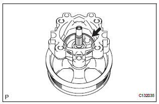
NOTICE: Before installation, coat the parts indicated by arrows with power steering fluid (See page PS-7).
1. INSTALL VANE PUMP HOUSING OIL SEAL
(a) Coat a new vane pump housing oil seal lip with power steering fluid.
(b) Using SST and a press, install the vane pump housing oil seal until it is flush with the vane pump front housing end surface.
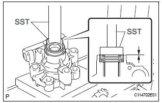
SST 09950-60010 (09951-00280), 09950-70010 (09951-07100)
NOTICE: Make sure that the oil seal is installed facing in the correct direction as shown in the illustration.
2. INSTALL VANE PUMP SHAFT WITH PULLEY
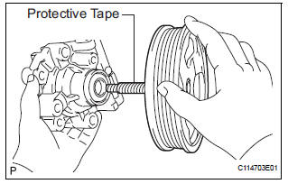
(a) Coat the inside surface of the bushing in the vane pump front housing with power steering fluid.
(b) Gradually insert the vane pump shaft with pulley.
NOTICE: Do not damage the oil seal lip in the front housing.
HINT: Wrap protective tape around the spline of the vane pump shaft with pulley in order to prevent damage to the oil seal.
3. INSTALL VANE PUMP FRONT SIDE PLATE
(a) Coat a new O-ring with power steering fluid and install it into the vane pump front housing.
(b) Coat a new O-ring with power steering fluid and install it onto the vane pump front side plate.
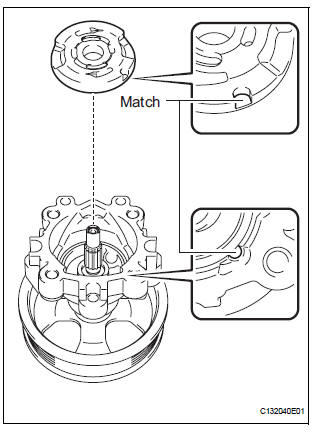
(c) Align the notch of the vane pump front side plate with that of the vane pump front housing, and install the vane pump front side plate.
NOTICE: Make sure that the vane pump front side plate is installed facing in the correct direction.
4. INSTALL VANE PUMP CAM RING
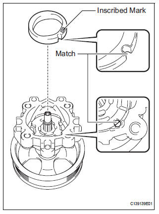
(a) Align the notch of the cam ring with that of the vane pump front side plate, and install the vane pump cam ring with the inscribed mark facing upward.
NOTICE: Make sure that the vane pump cam ring is installed facing in the correct direction.
5. INSTALL VANE PUMP ROTOR
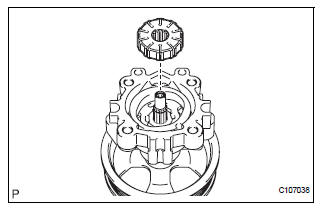
(a) Install the vane pump rotor.
HINT: The vane pump rotor can be installed in both directions.
(b) Coat the 10 vane pump plates with power steering fluid.
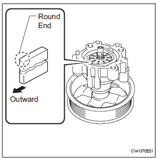
(c) Install the vane pump plates with the round end facing outward.
NOTICE: Make sure that the vane pump plates are installed facing in the correct direction.
6. INSTALL VANE PUMP SHAFT SNAP RING
(a) Using a screwdriver and a snap ring expander, install a new vane pump shaft snap ring onto the vane pump shaft with pulley.
NOTICE: Make sure that the vane pump shaft snap ring is securely installed in the vane pump shaft groove.
7. INSTALL VANE PUMP REAR HOUSING
(a) Coat a new O-ring with power steering fluid and install it onto the vane pump rear housing.
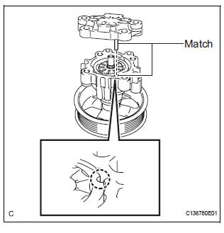
(b) Align the straight pin of the vane pump rear housing with the notches of the vane pump cam ring, vane pump front side plate, and vane pump front housing.
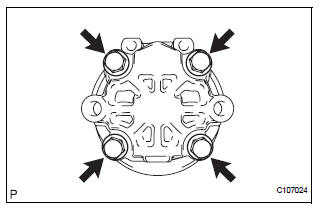
(c) Install the vane pump rear housing to the vane pump front housing with the 4 bolts.
Torque: 22 N*m (224 kgf*cm, 16 ft.*lbf)
8. INSPECT TOTAL PRELOAD (See page PS-14)
9. INSTALL FLOW CONTROL VALVE ASSEMBLY
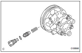
(a) Coat the flow control valve assembly with power steering fluid.
(b) Install the flow control valve compression spring and the flow control valve assembly to the vane pump front housing.
(c) Coat a new O-ring with power steering fluid and install it onto the pressure port union.
(d) Install the pressure port union to the vane pump front housing.
Torque: 69 N*m (704 kgf*cm, 51 ft.*lbf)
10. INSTALL POWER STEERING FLUID PRESSURE SWITCH
(a) Coat the O-ring attached to the new power steering fluid pressure switch with power steering fluid.
(b) Install the power steering fluid pressure switch to the vane pump front housing.
Torque: 21 N*m (214 kgf*cm, 16 ft.*lbf)
NOTICE: Do not use a power steering fluid pressure switch that has been subjected to an impact; for example, a power steering fluid pressure switch that has been dropped.
11. INSTALL POWER STEERING SUCTION PORT UNION
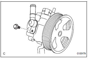
(a) Coat a new O-ring with power steering fluid and install it to the power steering suction port union.
(b) Install the power steering suction port union to the vane pump front housing with the bolt.
Torque: 12 N*m (122 kgf*cm, 9 ft.*lbf)
 Inspection
1. INSPECT VANE PUMP SHAFT AND BUSHING IN VANE PUMP FRONT HOUSING
(a) Using a micrometer, measure the outer diameter [a]
of the vane pump shaft with pulley.
(b) Using vernier calipers, measur ...
 Installation
1. INSTALL VANE PUMP ASSEMBLY
(a) Temporarily install the bolt to the vane pump
assembly.
(b) Install the vane pump assembly.
(c) Temporarily install the bolt (B).
(d) Using SST, tigh ...
Other materials:
Reassembly
1. INSTALL LH REAR BUMPER SIDE RETAINER
Install the LH rear bumper side retainer with the 3
screws.
2. INSTALL RH REAR BUMPER SIDE RETAINER
Install the RH rear bumper side retainer with the 3
screws.
3. INSTALL REAR BUMPER REINFORCEMENT SUBASSEMBLY
Install the rear bumper reinf ...
Removal
1. REMOVE BATTERY (See page EM-26)
2. REMOVE NO. 2 AIR CLEANER INLET (See page EM-
28)
3. REMOVE AIR CLEANER CAP SUB-ASSEMBLY (See
page FU-13)
4. REMOVE AIR CLEANER FILTER ELEMENT (See page
EM-28)
5. REMOVE AIR CLEANER CASE SUB-ASSEMBLY (See
page EM-28)
6. REMOVE AIR CLEANER BRACKET
(a ...
System description
1. OUTLINE OF THEFT DETERRENT SYSTEM
When the theft deterrent system detects that the
vehicle is being tampered with, the system sets off
the alarm, causing the horns to sound and the lights
to light up or blink in order to alert people around the
vehicle to the theft.
The ...
