Toyota Sienna Service Manual: SM Solenoid Circuit
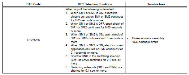
DTC C1225/25 SM Solenoid Circuit
DESCRIPTION
This solenoid turns on when receiving signals the ECU and controls the pressure acting on the wheel cylinders to control the braking force.
WIRING DIAGRAM
Refer to DTCs C0226/21, C0236/22, C0246/23 and C0256/24 (See page BC-105).
INSPECTION PROCEDURE
1 RECONFIRM DTC
(a) Clear the DTCs (See page BC-82).
(b) Turn the ignition switch to the ON position.
(c) Are the same DTCs recorded?
Result 
NOTICE: When replacing brake actuator assembly, perform zero point calibration (See page BC-70).

REPLACE BRAKE ACTUATOR ASSEMBLY
 Zero Point Calibration of Yaw Rate Sensor Undone
DESCRIPTION
The skid control ECU receives signals from the yaw rate sensor via CAN
communication system.
Yaw rate sensor has the built-in deceleration sensor.
If there is trouble in the b ...
 Steering Angle Sensor Circuit Malfunction
DTC C1231/31 Steering Angle Sensor Circuit Malfunction
DESCRIPTION
The steering angle sensor signal is sent to the skid control ECU through the
CAN communication system.
When there is a malfunc ...
Other materials:
Checking monitor status
The purpose of the monitor result (mode 06) is to allow
access to the results for on-board diagnostic monitoring tests
of specific components/systems that are not continuously
monitored. Examples are catalyst, evaporative emission
(EVAP) and thermostat.
The monitor result allows the OBD II sc ...
Brake Switch "A" Circuit
DTC P0571 Brake Switch "A" Circuit
DESCRIPTION
When the brake pedal is depressed, the stop light switch sends a signal to
the ECM. When the ECM
receives this signal, it cancels the cruise control. The fail-safe function
operates to enable normal driving
even if there is a malfuncti ...
Disassembly
1. REMOVE BRAKE MASTER LESS RESERVOIR TANK CYLINDER SUB-ASSEMBLY
(a) Using soft jaws on the vise, hold the brake master
cylinder in a vise through aluminum plates.
(b) Using a screwdriver, remove the O-ring.
(c) Using SST, remove the brake tube from the brake
master cylinder.
SST 09023 ...
