Toyota Sienna Service Manual: Inspection
1. INSPECT WINDSHIELD WIPER MOTOR ASSEMBLY
- LO Operation Check
- Connect the battery (+) to the terminal 1 (+1) of the connector, the battery (-) to the terminal 5 (E) of the connector, and check that the motor operates at low speed (LO).
- HI Operation Check
- Connect the battery (+) to the terminal 4 (+2) of the connector, the battery (-) to the terminal 5 (E) of the connector, and check that the motor operates at high speed (HI).
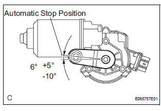
- Automatic Stop Operation Check
- Connect the battery (+) to the terminal 1 (+1) of the connector, the battery (-) to the terminal 5 (E) of the connector. With the motor being rotated at low speed (LO), disconnect terminal 1 (+1) to stop the wiper motor operation at any position except the automatic stop position.
- Using SST, connect the terminal 1 (+1) and 3
(S), and the battery (+) to the terminal 2 (B) to
restart the motor operation at low speed (LO).
SST 09843-18040
- Check the automatic stop position.
Standard: See the illustration.
 Removal
1. REMOVE FRONT WIPER ARM HEAD CAP
Using a small screwdriver, remove the 2 front wiper
arm covers.
HINT:
Tape up the screwdriver tip before use.
2. REMOVE FR WIPER ARM RH
&nbs ...
 Installation
1. INSTALL WINDSHIELD WIPER MOTOR ASSEMBLY
Apply MP grease to the crank arm pivot of the
windshield wiper motor assembly.
Install the windshield wiper motor assembly with the
...
Other materials:
Perform zero point calibration of yaw rate and deceleration sensor (when
using sst check wire)
NOTICE:
While obtaining the zero point, do not vibrate the
vehicle by tilting, moving or shaking it and keep it
in a stationary condition. (Do not turn the ignition
switch to the ON position.)
Be sure to do this on a level surface (with an
inclination of less than 1 %).
(a) Proc ...
Driving in vehicle-to-vehicle distance control mode
This mode employs a radar sensor to detect the presence of vehicles
up to approximately 400 ft. (120 m) ahead, determines the current
vehicle-to-vehicle following distance, and operates to maintain a suitable
following distance from the vehicle ahead.
Note that vehicle-to-vehicle distance will ...
Removal
HINT:
Replace the RH side by the same procedures as the LH side.
1. REMOVE REAR WHEEL
2. REMOVE REAR AXLE SHAFT LH NUT (See page DS-
22)
3. SEPARATE REAR DISC BRAKE CALIPER
ASSEMBLY LH
(a) Removing the 2 bolts, separate the rear disc brake
caliper assembly LH.
4. REMOVE REAR DISC
5. SEPARA ...
