Toyota Sienna Service Manual: Installation
1. INSTALL THROTTLE BODY
(a) Install a new throttle body gasket to the intake air surge tank.
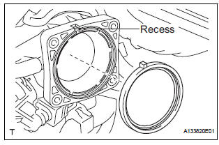
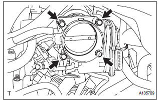
(b) Install the throttle body with the 4 bolts.
Torque: 10 N*m (102 kgf*cm, 7 ft.*lbf)
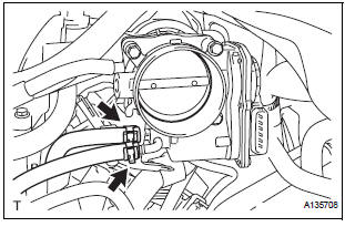
(c) Connect the 2 water by-pass hoses.
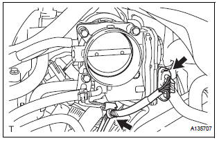
(d) Connect the throttle body connector and clamp.
2. INSTALL AIR CLEANER CASE SUB-ASSEMBLY (See page EM-59)
3. INSTALL AIR CLEANER CAP SUB-ASSEMBLY
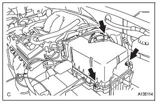
(a) Install the air cleaner cap sub-assembly with the 2 bolts.
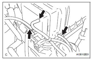
(b) Connect the the vacuum hose (EVAP) to the air cleaner hose.
(c) Install the No. 2 ventilation hose and air cleaner hose band.
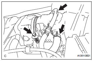
(d) Connect the 3 vacuum hoses.
4. INSTALL NO. 1 AIR CLEANER INLET (See page EM- 59) 5. INSTALL NO. 2 AIR CLEANER INLET (See page EM- 60) 6. ADD ENGINE COOLANT (See page CO-7) 7. INSPECT FOR ENGINE COOLANT LEAK (See page CO-1) 8. INSTALL V-BANK COVER SUB-ASSEMBLY (See page EM-63) 9. INSTALL FRONT OUTER COWL TOP PANEL SUBASSEMBLY (See page EM-61) 10. INSTALL WINDSHIELD WIPER MOTOR ASSEMBLY
HINT: (See page WW-5)
 Removal
1. Remove windshield wiper motor assembly
hint:
(see page ww-4)
2. Remove front outer cowl top panel subassembly
(see page em-27)
3. Drain engine coolant (see page co-6)
4. Remove v-bank cover s ...
 ECM
ECM
COMPONENTS
REMOVAL
1. REMOVE GLOVE COMPARTMENT DOOR ASSEMBLY
(a) Push the right side wall and then push the left wall
to release the stoppers.
(b) Pull the glove compartment door sub-as ...
Other materials:
Vehicle Speed Sensor "A"
DESCRIPTION
The speed sensor detects the wheel speed and sends the appropriate signals to
the skid control ECU.
The skid control ECU converts these wheel speed signals into a 4-pulse signal
and outputs it to the ECM
via the combination meter. The ECM determines the vehicle speed based o ...
System description
1. GENERAL
To assist the driver with parking the vehicle by
displaying an image of the area behind the vehicle,
this system has a television camera mounted on the
luggage compartment door. The system displays
the image on the radio and navigation assembly.
This system consi ...
Fold Lock Switch Circuit
DESCRIPTION
Each of the left and right seats has a fold lock switch that detects the lock
condition of the seat legs and
floor when the seat is in the stowed state. If the fold lock switch detects an
unlock condition, the 3rd SEAT
indicator on the combination meter will come on.
WIRING DIAGR ...
