Toyota Sienna Service Manual: Removal
1. REMOVE FRONT WIPER ARM HEAD CAP
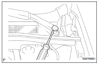
- Using a small screwdriver, remove the 2 front wiper arm covers.
HINT: Tape up the screwdriver tip before use.
2. REMOVE FR WIPER ARM RH
- Operate the wiper, and stop the windshield wiper motor assembly to the automatic stop position.
- Remove the nut and the FR wiper arm RH.
3. REMOVE FR WIPER ARM LH
- Remove the nut and the FR wiper arm LH.
4. REMOVE COWL TOP VENTILATOR LOUVER SUBASSEMBLY
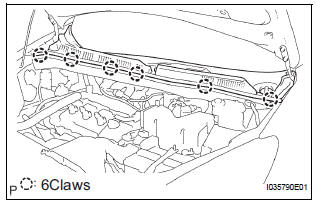
- Remove the 6 claws and the cowl top ventilator louver sub-assembly.
5. REMOVE WINDSHIELD WIPER MOTOR AND LINK ASSEMBLY
- Disconnect the connector.
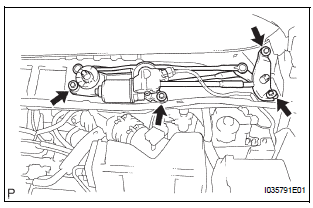
- Remove the 4 bolts and wiper motor & link assembly.
6. REMOVE WINDSHIELD WIPER MOTOR ASSEMBLY
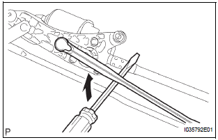
- Using a screwdriver, disengage the meshing of rod at the crank arm pivot of the windshield wiper motor assembly.
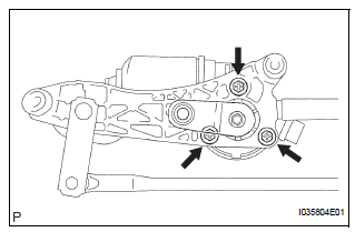
- Remove the 3 bolts and windshield wiper motor assembly from the windshield wiper link assembly.
HINT: Turning the crank arm by hand prior to the operation will be able to remove the wiper motor easier.
 Front wiper motor
COMPONENTS
...
 Inspection
1. INSPECT WINDSHIELD WIPER MOTOR ASSEMBLY
LO Operation Check
Connect the battery (+) to the terminal 1 (+1) of
the connector, the battery (-) to the terminal 5
(E) of th ...
Other materials:
Skid Control Buzzer Circuit
DESCRIPTION
The skid control buzzer sounds and SLIP indicator blinking during VSC
operation.
WIRING DIAGRAM
INSPECTION PROCEDURE
1 PERFORM ACTIVE TEST USING INTELLIGENT TESTER (SKID CONTROL BUZZER)
(a) Connect the intelligent tester to the DLC3.
(b) Start the engine.
(c) Select the ...
Turning the high beam on/off manually
Switching to low beam
Pull the lever to the original
position.
Switching to high beam
Turn the light switch to the
position.
The Automatic High Beam can be operated when
The engine switch is in the “ON” position (vehicles without a smart key
system)
or IGNITION ON mode (vehicl ...
Turn signal light switch
ON-VEHICLE INSPECTION
1. INSPECT TURN SIGNAL FLASHER CIRCUIT
Measure voltage between the terminals as shown in
the chart below.
Voltage
Connect the connector to turn the signal flasher and
turn the ignition switch ON, and inspect the wire
harness side connector from t ...
