Toyota Sienna Service Manual: Removal
1. REMOVE INSTRUMENT PANEL SAFETY PAD SUBASSEMBLY
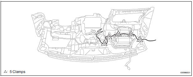
2. REMOVE ANTENNA CORD SUB-ASSEMBLY
- Replace the 5 clamps and remove the antenna cord sub-assembly.
3. REMOVE PULL TOP ANTENNA POLE SUBASSEMBLY
4. REMOVE ANTENNA ORNAMENT
- Remove the antenna ornament.
5. REMOVE ANTENNA ASSEMBLY WITH HOLDER
- Disconnect the connector and remove the bolt.
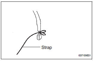
- Tie the string at the tip of the cable of the antenna assembly with holder.
HINT: Leave the string in the vehicle. It will be used when installing the antenna assembly with holder.
- Remove the nut and the antenna assembly with holder.
6. REMOVE ROOF HEADLINING ASSEMBLY
7. REMOVE AMPLIFIER ANTENNA ASSEMBLY
- Disconnect the connectors.
- Remove the 3 bolts.
- Disengage the 16 clamps and remove the amplifier antenna assembly.
 Radio antenna cord
COMPONENTS
...
 Installation
1. INSTALL AMPLIFIER ANTENNA ASSEMBLY
Engage the 16 clamps to install the amplifier
antenna assembly.
Install the 3 bolts.
Connect the connectors.
2. INSTALL ROOF HEAD ...
Other materials:
Installation
1. INSTALL THROTTLE BODY
Install a new throttle body gasket to the intake air
surge tank.
Install the throttle body with the 4 bolts.
Torque: 10 N*m (102 kgf*cm, 7 ft.*lbf)
Connect the 2 water by-pass hoses.
Connect the throttle body connector and clamp.
2. ...
Precaution
1. Check that the battery cables are connected to the
correct terminals.
2. Disconnect the battery cables when the battery is
given a quick charge.
3. Do not perform tests with a high voltage insulation
resistance tester.
4. Never disconnect the battery cables while the engine
is runnin ...
Short to B+ in CAN Bus Line
DESCRIPTION
A short to B+ is suspected in the CAN bus wire when the resistance between
terminals 6 (CANH) and 16
(BAT), or terminals 14 (CANL) and 16 (BAT) of the DLC3 is below 6 kΩ.
Symptom
Trouble Area
The resistance between terminals 6 (CANH) and 16 (BAT), or
...
