Toyota Sienna Service Manual: Inspection
1. INSPECT CAMSHAFT TIMING OIL CONTROL VALVE ASSEMBLY
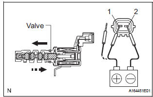
- Resistance inspection
- Using an ohmmeter, measure the resistance
between the terminals.
Resistance: 6.9 to 7.9 Ω at 20C (68F) If necessary, replace the camshaft timing oil control valve assembly.
- Movement inspection
- Connect the positive (+) lead from the battery to terminal 1 and connect the negative (-) lead to terminal 2, and check the movement of the valve.
NOTICE: Confirm that the valve moves freely and does not stick in any position.
If necessary, replace the camshaft timing oil control valve assembly.
HINT: Accumulation of foreign objects causes subtle pressure leaks. The subtle pressure leaks will cause the cam to advance, and this will cause a DTC to be set.
 On-vehicle inspection
1. INSPECT CAMSHAFT TIMING CONTROL VALVE ASSEMBLY
Connect the intelligent tester to the DLC3.
Turn the ignition switch to the ON position.
Start the engine and warm it up ...
 Installation
1. INSTALL CAMSHAFT TIMING OIL CONTROL VALVE ASSEMBLY (for Bank 2 Exhaust
Side)
Apply a light coat of engine oil to the new O-ring and
install it to the camshaft timing oil control v ...
Other materials:
No. 1 Ultrasonic sensor
COMPONENTS
REMOVAL
1. REMOVE FRONT FENDER LINER LH
2. REMOVE FRONT FENDER LINER RH
3. REMOVE FRONT BUMPER COVER
4. REMOVE REAR BUMPER COVER (2)
5. REMOVE NO. 1 ULTRASONIC SENSOR RETAINER
Remove the No. 1 ultrasonic sensor retainer as
shown in the illustration
6. REMOVE ...
Cold Start Ignition Timing Performance
DESCRIPTION
This monitor will run when the engine is started at -10 to 50┬░C (14 to 122┬░F)
of the engine coolant
temperature. The DTC will set after the engine idling for 13 seconds (2 trip
detection logic).
The DTC is designed to monitor the idle air control at cold start. When the
...
Removal
HINT:
Use the same procedures for the RH side and LH side.
The procedures listed below are for the LH side.
1. PRECAUTION
CAUTION:
Be sure to read "PRECAUTION" thoroughly before servicing.
2. DISCONNECT CABLE FROM NEGATIVE BATTERY
TERMINAL
CAUTION:
Wait for 90 se ...
