Toyota Sienna Service Manual: Installation
1. INSTALL CAMSHAFT TIMING OIL CONTROL VALVE ASSEMBLY (for Bank 2 Exhaust Side)
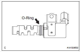
- Apply a light coat of engine oil to the new O-ring and install it to the camshaft timing oil control valve.
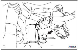
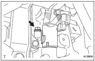
- Install the camshaft timing oil control valve
assembly with the bolt.
Torque: 10 N*m (102 kgf*cm, 7 ft.*lbf)
- Connect the camshaft timing oil control valve assembly connector
2. INSTALL CAMSHAFT TIMING OIL CONTROL VALVE ASSEMBLY (for Bank 2 Intake Side)
- Apply a light coat of engine oil to the new O-ring and install it to the camshaft timing oil control valve.
- Install the camshaft timing oil control valve
assembly with the bolt.
Torque: 10 N*m (102 kgf*cm, 7 ft.*lbf) Connect the camshaft timing oil control valve assembly connector
3. INSTALL CAMSHAFT TIMING OIL CONTROL VALVE ASSEMBLY (for Bank 1 Exhaust Side)
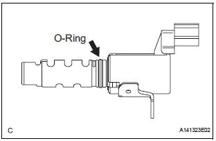
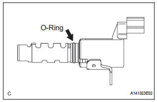
- Apply a light coat of engine oil to the new O-ring and install it to the camshaft timing oil control valve.
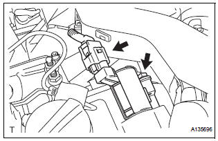
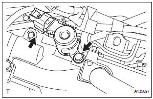
- Install the camshaft timing oil control valve
assembly with the bolt.
Torque: 10 N*m (102 kgf*cm, 7 ft.*lbf)
- Connect the camshaft timing oil control valve assembly connector
4. INSTALL CAMSHAFT TIMING OIL CONTROL VALVE ASSEMBLY (for Bank 1 Intake Side)
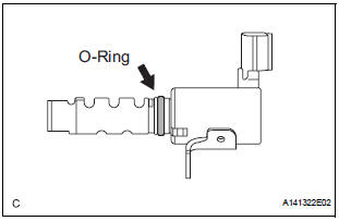
- Apply a light coat of engine oil to the new O-ring and install it to the camshaft timing oil control valve.
- Install the camshaft timing oil control valve
assembly with the bolt.
Torque: 10 N*m (102 kgf*cm, 7 ft.*lbf)
- Connect the camshaft timing oil control valve assembly connector.
5. INSTALL INTAKE AIR SURGE TANK ASSEMBLY
6. INSTALL AIR CLEANER CASE SUB-ASSEMBLY
7. INSTALL AIR CLEANER CAP SUB-ASSEMBLY
8. INSTALL NO. 1 AIR CLEANER INLET
9. INSTALL NO. 2 AIR CLEANER INLET
10. ADD ENGINE COOLANT
11. INSPECT FOR ENGINE COOLANT LEAK
12. INSPECT FOR ENGINE OIL LEAK
13. INSTALL V-BANK COVER SUB-ASSEMBLY
14. INSTALL FRONT OUTER COWL TOP PANEL SUBASSEMBLY
15. INSTALL WINDSHIELD WIPER MOTOR ASSEMBLY
 Inspection
1. INSPECT CAMSHAFT TIMING OIL CONTROL VALVE ASSEMBLY
Resistance inspection
Using an ohmmeter, measure the resistance
between the terminals.
Resistance:
6.9 to 7.9 ] ...
 Throttle body
...
Other materials:
Removal
HINT:
On the RH side, use the same procedures as on the LH side.
1. REMOVE BACK DOOR STAY SUB-ASSEMBLY LH
Remove the 2 bolts and disconnect the stay from
the body panel.
Using the screwdriver, disengage the clips and
remove the stay from the door panel.
Remove the bolt from door pa ...
Back Door Closer Switch Malfunction
DTC B2215 Back Door Closer Switch Malfunction
DESCRIPTION
This DTC is output when a malfunction occurs in the position switch in the
back door. This position switch
detects if the back door is in the latch position and sends a position signal to
the power back door ECU.
DTC No.
...
Reclining Motor Circuit
DESCRIPTION
The fold seat control ECU receives a switch operation signal from the power
rear no. 2 seat switch and
the fold seat switch, and activates the reclining motor. At this time, the Hall
IC (seatback position sensor)
detects the actuation of the seatback and sends a seatback actuation ...
