Toyota Sienna Service Manual: On-vehicle inspection
1. INSPECT CAMSHAFT TIMING CONTROL VALVE ASSEMBLY
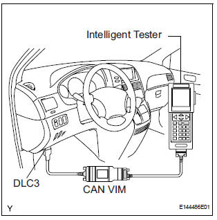
- Connect the intelligent tester to the DLC3.
- Turn the ignition switch to the ON position.
- Start the engine and warm it up.
- Select the intelligent tester from the ACTIVE TEST menu.
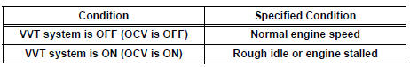
- Check the engine speed when the OCV (camshaft timing oil control valve) is operated by the intelligent tester.
OK
REMOVAL
1. REMOVE WINDSHIELD WIPER MOTOR ASSEMBLY
2. REMOVE FRONT OUTER COWL TOP PANEL SUBASSEMBLY
3. DRAIN ENGINE COOLANT
4. REMOVE V-BANK COVER SUB-ASSEMBLY
5. REMOVE NO. 2 AIR CLEANER INLET
6. REMOVE NO. 1 AIR CLEANER INLET
7. REMOVE AIR CLEANER CAP SUB-ASSEMBLY
8. REMOVE AIR CLEANER CASE SUB-ASSEMBLY
9. REMOVE INTAKE AIR SURGE TANK ASSEMBLY
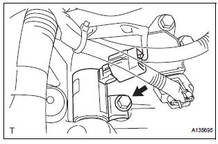
10. REMOVE CAMSHAFT TIMING OIL CONTROL VALVE ASSEMBLY (for Bank 1 Exhaust Side)
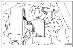
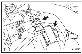
- Disconnect the camshaft timing oil control valve assembly connector.
- Remove the bolt and camshaft timing oil control valve assembly.
- Remove the O-ring from the camshaft timing oil control valve.
11. REMOVE CAMSHAFT TIMING OIL CONTROL VALVE ASSEMBLY (for Bank 1 Intake Side)
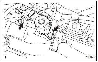
- Disconnect the camshaft timing oil control valve assembly connector.
- Remove the bolt and camshaft timing oil control valve assembly.
- Remove the O-ring from the camshaft timing oil control valve.
12. REMOVE CAMSHAFT TIMING OIL CONTROL VALVE ASSEMBLY (for Bank 2 Exhaust Side)
- Disconnect the camshaft timing oil control valve assembly connector.
- Remove the bolt and camshaft timing oil control valve assembly.
- Remove the O-ring from the camshaft timing oil control valve.
13. REMOVE CAMSHAFT TIMING OIL CONTROL VALVE ASSEMBLY (for Bank 2 Intake Side)
- Disconnect the camshaft timing oil control valve assembly connector.
- Remove the bolt and camshaft timing oil control valve assembly.
- Remove the O-ring from the camshaft timing oil control valve.
 Components
...
 Inspection
1. INSPECT CAMSHAFT TIMING OIL CONTROL VALVE ASSEMBLY
Resistance inspection
Using an ohmmeter, measure the resistance
between the terminals.
Resistance:
6.9 to 7.9 ] ...
Other materials:
Summary of the Blind Spot Monitor
The Blind Spot Monitor is a system that has 2 functions:
The Blind Spot Monitor function
Assists the driver in making the decision when changing lanes
The Rear Cross Traffic Alert function
Assists the driver when backing up
These functions use same sensors.
BSM main switch
Pre ...
Removal
1. PRECAUTION
CAUTION:
Be sure to read "PRECAUTION" thoroughly before servicing.
2. DISCONNECT CABLE FROM NEGATIVE BATTERY
TERMINAL
CAUTION:
Wait for 90 seconds after disconnecting the cable to
prevent the airbag working.
3. REMOVE FRONT SEAT ASSEMBLY (for Manual Seat)
4. REMOVE F ...
Dtc check / clear
1. DTC CHECK (NORMAL MODE)
NOTICE:
When the diagnostic system is switched from the
normal mode to the check mode, all the DTCs and
freeze frame data recorded in the normal mode will
be erased. So before switching modes, always check
the DTCs and freeze frame data, and note the ...
