Toyota Sienna Service Manual: Inspection
1. INSPECT FRONT SEAT INNER BELT ASSEMBLY RH
- Release the seat belt (Buckle switch is ON).
- Check the resistance between the terminals.
Standard
If the result is not as specified, replace the inner belt assembly.
- Inspect the buckle switch.
- Fasten the seat belt (Buckle switch is OFF).
- Check the resistance between the terminals.
Standard
- Inspect the circuit for the airbag seat position sensor.
- Check the resistance between the terminals.
Standard
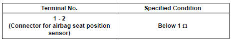
If the result is not as specified, replace the seat cushion assembly.
2. INSPECT FRONT SEAT INNER BELT ASSEMBLY LH
- Inspect the buckle switch.
- Fasten the seat belt (Buckle switch is ON).
- Check the resistance between the terminals.
Standard
- Release the seat belt (Buckle switch is OFF).
- Check the resistance between the terminals.
Standard
If the result is not as specified, replace the inner belt assembly.
 Removal
1. REMOVE FRONT SEAT INNER BELT ASSEMBLY
HINT:
Refer to the instructions for disassembly of the front
seat assembly (for flat type).
Refer to the instructions for disassembly of t ...
 Installation
1. REMOVE FRONT SEAT INNER BELT ASSEMBLY
HINT:
Refer to the instructions for reassembly of the front
seat assembly (for flat type).
Refer to the instructions for reassembly of the ...
Other materials:
Inspection
1. INSPECT FRONT STABILIZER LINK ASSEMBLY LH
(a) As shown in the illustration, flip the ball joint stud
back and forth 5 times, before installing the nut.
(b) Using a torque wrench, turn the nut continuously at
a rate of 2 to 4 seconds per 1 turn and take the
torque reading on the 5th turn.
...
Disposal
1. DISPOSE OF SHOCK ABSORBER ASSEMBLY REAR LH
(a) Fully extend the shock absorber rod.
(b) Using a drill, make a hole in the cylinder as shown in
the illustration to discharge the gas inside the
cylinder.
CAUTION:
When drilling, since the fragments may fly
out, work careful ...
Camshaft Position "B" Actuator Circuit
DESCRIPTION
The Variable Valve Timing (VVT) system includes the ECM, OCV and VVT
controller. The ECM sends a
target duty-cycle control signal to the OCV. This control signal regulates the
oil pressure supplied to the
VVT controller. Camshaft timing control is performed according to engine ...
