Toyota Sienna Service Manual: Inspection
1. V
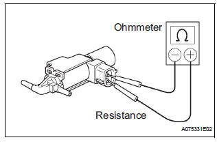
(a) Inspect VSV operation.
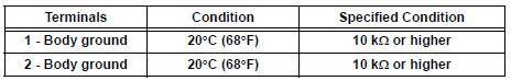
(1) Using an ohmmeter, measure the resistance according to the value(s) in the table below.V
Standard resistance
If the result is not as specified, replace the vsv.
(B) inspect the vsv for ground.
(1) Using an ohmmeter, measure the resistance according to the value(s) in the table below.
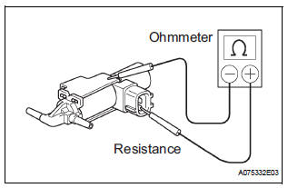
Standard resistance
If the result is not as specified, replace the vsv.
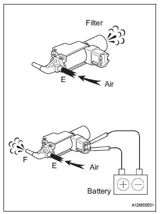
(2) Inspect vsv operation.
- Check that air flows from port E to the filter.
- Apply battery voltage across the terminals.
- Check that air flows from port E to port F.
If operation is not as specified, replace the VSV.
 Vacuum switching valve
Components
REMOVAL
1. REMOVE VACUUM SWITCHING VALVE ASSEMBLY
(a) Remove the 2 vacuum hoses and vacuum switching
valve connector.
(b) Remove the screw and vacuum switching valve. ...
 Installation
1. Install vacuum switching valve assembly
(a) Install the vacuum switching valve with the screw.
(b) Install the 2 vacuum hoses and vacuum switching
valve connector. ...
Other materials:
Passenger Airbag ON/OFF Indicator Circuit
Malfunction
DTC B1152/28 Passenger Airbag ON/OFF Indicator Circuit
Malfunction
DESCRIPTION
The passenger airbag ON/OFF indicator circuit consists of the center airbag
sensor assembly and
passenger airbag ON/OFF indicator.
This circuit indicates the operation condition of the front passenger airbag,
t ...
TC and CG Terminal Circuit
DESCRIPTION
Connecting terminals TC and CG of the DLC3 causes the ECU to display the DTC
by blinking the ABS
warning light and/or VSC warning light.
WIRING DIAGRAM
INSPECTION PROCEDURE
NOTICE:
When replacing the brake actuator assembly, perform zero point calibration
(See page BC-70).
...
Closing the fuel tank cap
After refueling, turn the fuel tank
cap until you hear a click. Once
the cap is released, it will turn
slightly in the opposite direction.
WARNINGWhen replacing the fuel tank cap
Do not use anything but a genuine Toyota fuel tank cap designed for
your
vehicle. Doing so may c ...
