Toyota Sienna Service Manual: Reassembly
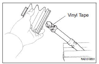
1. INSTALL REAR DRIVE SHAFT OUTBOARD JOINT BOOT
HINT: Before install the boot, wrap the spline of the outboard joint shaft with vinyl tape to prevent the boot from bearing damaged.
(a) Install new outboard joint boot, 2 outboard joint boot clamps, 2 inboard joint boot clamps and inboard joint boot.
(b) Make sure that the 2 boots are on the shaft groove.
2. INSTALL REAR DRIVE SHAFT OUTBOARD JOINT BOOT CLAMP
(a) Hold the drive shaft lightly in a soft vise.
(b) Install the 2 outboard joint boot clamps to the boot.
HINT: Before install the clamps, pack the outboard joint and boot with grease in the boot kit.
Grease capacity: 90 to 110 g (3.2 to 3.9 oz.)
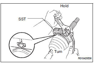
(c) Place SST onto the 2 outboard joint boot clamps.
SST 09521-24010
(d) Tighten the SST so that the 2 outboard joint boot clamps is pinched.
NOTICE: Do not overtighten the SST.
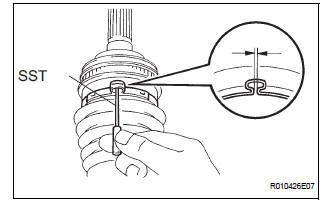
(e) Using a SST, measure the clearance of the 2 outboard joint boot clamps.
SST 09240-00020 Clearance: 1.2 to 4.0 mm (0.047 to 0.157 in.)
NOTICE: When the measured value is greater than the specified value, retighten the clamp.
3. INSTALL REAR DRIVE SHAFT INBOARD JOINT ASSEMBLY
(a) Through a new inboard joint boot, 2 new inboard joint clamps and cage.
(b) Align the matchmarks, using a brass bar and a hammer, install the inner race.
(c) Using a snap ring expander, install a new rear drive shaft snap ring.
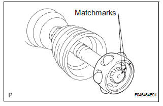
(d) Align the matchmarks, install the cage to the inner race.
(e) Install the 6 balls with grease to the inner race.
(f) Pack the inboard joint shaft and boot with grease in the boot kit.
Grease capacity: 130 to 150 g (4.6 to 5.3 oz.)
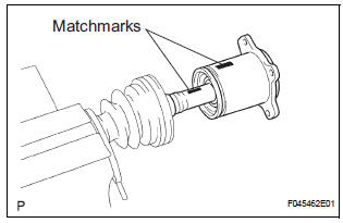
(g) Align the matchmarks, install the inboard joint assembly to the outboard joint shaft assembly.
(h) Install the clip.
4. INSTALL REAR DRIVE SHAFT INBOARD JOIN BOOT
(a) Install the inboard joint boot to the rear drive shaft inboard joint.
5. INSTALL REAR DRIVE SHAFT INBOARD JOINT BOOT CLAMP
(a) Using a screwdriver, install the No. 2 rear drive shaft inboard joint boot clamp.
(b) Install the inboard joint boot clamp by the same procedures as the No. 2 rear drive shaft inboard joint boot clamp.
 Inspection
1. INSPECT REAR DRIVE SHAFT ASSEMBLY LH
(a) Check that there is no remarkable play in the radial
direction of the outboard joint.
(b) Check that the inboard joint slides smoothly in the
thru ...
 Installation
1. INSTALL REAR DRIVE SHAFT ASSEMBLY LH
(a) Install the drive shaft to the axle carrier.
NOTICE:
Be careful not to damage the boot and ABS
speed sensor rotor to the drive shaft and oil seal
o ...
Other materials:
Installation
1. INSTALL WINDSHIELD WIPER MOTOR ASSEMBLY
Apply MP grease to the crank arm pivot of the
windshield wiper motor assembly.
Install the windshield wiper motor assembly with the
3 bolts to the windshield wiper link assembly.
Torque: 7.5 N*m (76 kgf*cm, 66 in.*lbf)
2. INST ...
Replying to a message
Display the message inbox screen.
Select the desired message from the list.
Select “Quick Message”.
Select the desired message.
Select “Send”.
If an error message is displayed, follow the guidance on the screen to try
again.
Editing quick reply message
Select “Quick ...
Park / Neutral Position Switch Circuit
DESCRIPTION
The fold seat control ECU receives signals from the Park/Neutral position
switch and controls the seat
stowing and return operations. If the shift lever is in any position other than
P the seat cannot be operated.
If the ignition switch is in ACC or IG the seat cannot be operate ...
