Toyota Sienna Service Manual: Inspection procedure
1 BASIC INSPECTION
- Check the conditions necessary for the power slide door to open:
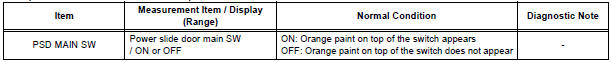
- Power slide door main switch is in the ON position (switch free: orange paint on the top of the switch appears).
- Slide door is unlocked (door lock position switch is in the ON position when the slide door is fully closed).
- Shift lever is in the P position when the ignition switch is ON (When the ignition switch is OFF, the power slide door operates at any position of the shift lever.)
- Check the conditions necessary for the power slide door to close:
- Power slide door main switch is in the ON position (switch free: orange paint on the top of the switch appears).
- Slide door is between approximately the half-open position and the fully open position.
- Slide door touch sensor is not damaged / deformed.
2 INSPECT FUSE (ECU-B)
- Inspect the ECU-B fuse.
3 CHECK DTC
- Check for DTC B2224, DTC B224 indicates a pulse sensor malfunction.
- Without code outputs, proceed to A.
- With code output, proceed to B.
4 INSPECT COMMUNICATION FUNCTION OF LARGE-SCALE BODY MULTIPLEX COMMUNICATION SYSTEM (BEAN)
- Use the intelligent tester to check for normal function of the multiplex communication system.
- (ECU unconnected, communication line malfunctioning) Without DTC B1214, B1215 or B1217 outputs, proceed to A.
- (ECU unconnected, communication line malfunctioning) With DTC B1214, B1215 or B1217 outputs, proceed to B.
5 READ VALUE OF INTELLIGENT TESTER
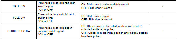
- Using the intelligent tester, check the DATA LIST for proper functioning of the power slide door main switch.
OK (Power slide door ECU LH):
6 INSPECT POWER SLIDE DOOR MAIN SWITCH
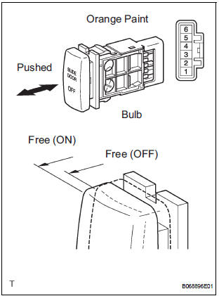
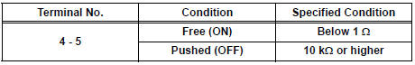
- Inspect the resistance of the main switch.
Resistance
HINT: If the switch does not illuminate, it will not affect the ON / OFF function of the switch
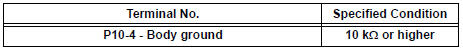
7 CHECK WIRE HARNESS (POWER SLIDE DOOR MAIN SWITCH - POWER SLIDE DOOR ECU LH)
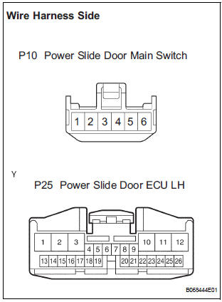
- Disconnect the P10 switch and P25 ECU connectors.
- Check the resistance between the wire harness side connectors.
Resistance (Check for open circuit)
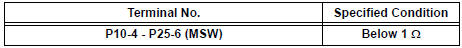
- Check the resistance between the P10 switch connector and body ground.
Resistance (Check for short circuit)
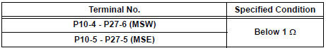
8 CHECK WIRE HARNESS (POWER SLIDE DOOR MAIN SWITCH - POWER SLIDE DOOR ECU RH)
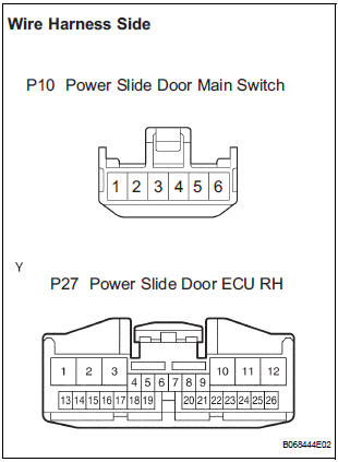
- Disconnect the P10 switch and P27 ECU connectors.
- Check the resistance between the wire harness side connectors.
Resistance (Check for open circuit)
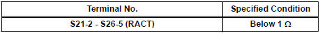
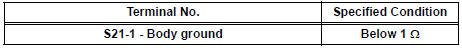
- Check the resistance between the S13 switch connector and body ground.
Resistance (Check for open circuit)
9 READ VALUE OF INTELLIGENT TESTER
- Using the intelligent tester, check the DATA LIST for proper functioning of the power slide door main switch.
OK (Power slide door ECU RH):

REPLACE POWER SLIDE DOOR ECU LH
10 CHECK SWITCH OPERATION
- If the power slide door does not respond to using the satellite switch, proceed to A.
- If the power slide door does not respond to using the power slide door control switch (child lock is set at UNLOCK.), proceed to B.
HINT: If the power slide door cannot operate using the power slide door control switch even when the child lock is unlocked, there may be a malfunction in the child lock switch. In this case, check the handle switch circuit.
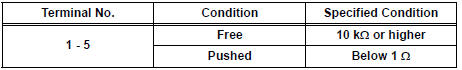
11 INSPECT SATELLITE SWITCH
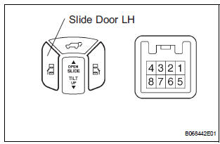
- Inspect the resistance of the LH switch.
Resistance
HINT: If the switch does not illuminate, it will not affect the ON / OFF function of the switch. For the illumination check, refer to SLIDE DOOR SYSTEM
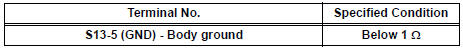
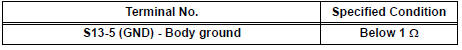
12 CHECK WIRE HARNESS (SATELLITE SWITCH - DRIVER SIDE J/B, BODY GROUND)
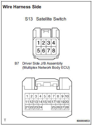
- Disconnect the S13 switch and B7 ECU connectors.
- Check the resistance between the wire harness side connectors.
Resistance (Check for open circuit)
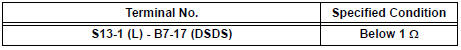
- Check the resistance between the S13 switch connector and body ground.
Resistance (Check for open circuit)
REPAIR OR REPLACE HARNESS AND CONNECTOR
13 READ VALUE OF INTELLIGENT TESTER
- Using the intelligent tester, check the DATA LIST for proper functioning of the power slide door control switch LH.
OK (Power slide door ECU LH):
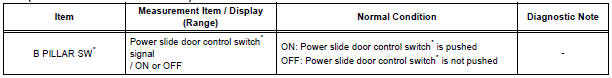
* "B PILLAR SW" appears on the display of the intelligent tester, however the name of the part corresponding to the display of the tester is "Power slide door control switch".
14 INSPECT POWER SLIDE DOOR CONTROL SWITCH LH
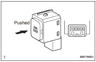
- Inspect the resistance of the switch.
Resistance
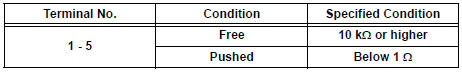
HINT: If the switch does not illuminate, it will not affect the ON / OFF function of the switch. For the illumination check, refer to SLIDE DOOR SYSTEM
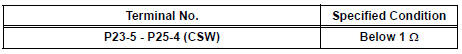
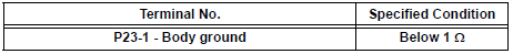
15 CHECK WIRE HARNESS (DOOR CONTROL SWITCH - POWER SLIDE DOOR ECU, BODY GROUND)
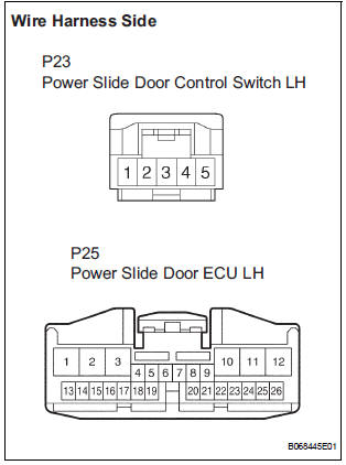
- Disconnect the P23 switch and P25 ECU connectors.
- Check the resistance between the wire harness side connectors.
Resistance (Check for open circuit)
- Check the resistance between the P23 switch connector and body ground.
Resistance (Check for open circuit)
REPLACE POWER SLIDE DOOR ECU LH
16 READ VALUE OF INTELLIGENT TESTER
- Using the intelligent tester, check that a power slide door touch sensor LH signal is output when the sensor is operated.
OK (Power slide door ECU LH):
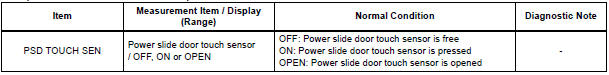
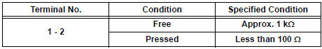
17 INSPECT POWER SLIDE DOOR TOUCH SENSOR LH
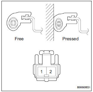
- Inspect the resistance of the sensor.
Resistance
18 CHECK WIRE HARNESS (POWER SLIDE DOOR TOUCH SENSOR LH - POWER SLIDE DOOR ECU LH)
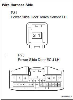
- Disconnect the P31 sensor and P25 ECU connectors.
- Check the resistance between the wire harness side connectors.
Resistance (Check for open circuit)
REPLACE POWER SLIDE DOOR ECU LH
19 READ VALUE OF INTELLIGENT TESTER
- Using the intelligent tester, check the DATA LIST for proper functioning of the fuel lid courtesy switch.
OK (Power slide door ECU LH):
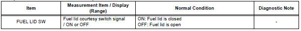
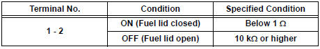
20 INSPECT FUEL LID COURTESY SWITCH
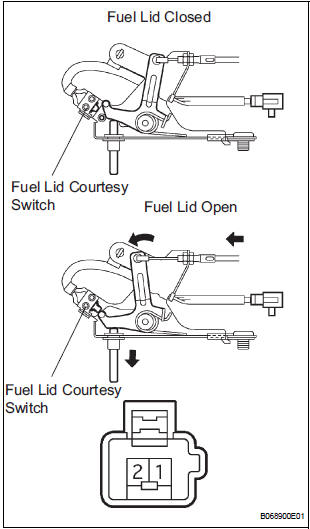
- Inspect the resistance of the switch.
Resistance
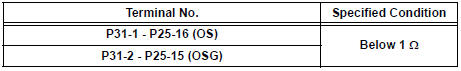
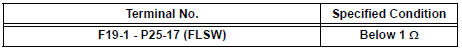
21 CHECK WIRE HARNESS (FUEL LID COURTESY SWITCH - DOOR ECU LH AND BODY GROUND)
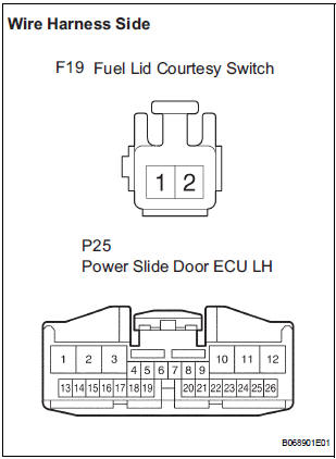
- Disconnect the F19 switch and P25 ECU connectors.
- Check the resistance between the wire harness side connectors.
Resistance (Check for open circuit)
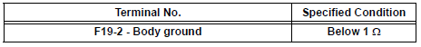
- Check the resistance between the F19 switch connector and body ground.
Resistance (Check for open circuit)
REPLACE POWER SLIDE DOOR ECU LH
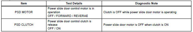
22 PERFORM ACTIVE TEST BY INTELLIGENT TESTER
- Select the ACTIVE TEST and then check that the power slide door control motor and clutch LH operates.
HINT: During the ACTIVE TEST, the intelligent tester sends a signal to the power slide door ECU LH to drive the motor and clutch. If the motor and clutch operate, the motor and clutch itself and the wire harness between the motor and clutch and the power slide door ECU LH are considered to be functioning normally.
OK (Power slide door ECU LH):
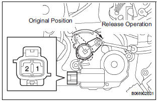
23 INSPECT SLIDE DOOR CONTROL MOTOR AND CLUTCH ASSEMBLY LH
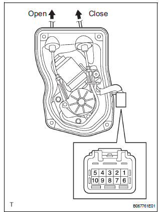
- Remove the motor and clutch.
- Connect the battery positive (+) lead to terminal 3 and battery negative (-) terminal lead to terminal 2.
- Apply battery voltage to the terminals and check the motor operation.
OK
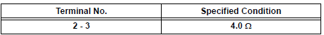
- Check the resistance of the clutch terminals.
Resistance
- Reinstall the motor and clutch with the connector connected.
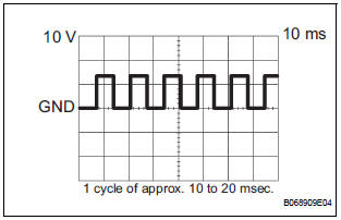
- Check the pulse of the pulse sensor
- Using an oscilloscope, check the pulse generated when the door is manually opened and closed.
Reference
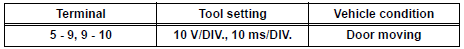
HINT: A cycle of the pulse changes between approx. 10 to 20 msec. according to the speeds that the slide door is moving.
NOTICE: When disconnecting the control motor and clutch, initialize the power slide door system
24 CHECK WIRE HARNESS (POWER SLIDE DOOR CONTROL MOTOR - POWER SLIDE DOOR ECU LH)
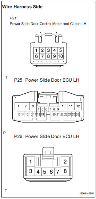
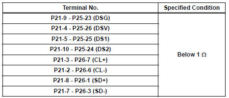
- Disconnect the P21 motor and clutch, the P25 and P26 ECU connectors.
- Check the resistance between the wire harness side connectors.
Resistance (Check for open circuit)
REPLACE POWER SLIDE DOOR ECU LH
25 READ VALUE OF INTELLIGENT TESTER
- Using the intelligent tester, check the DATA LIST for proper functioning of the switches listed below.
OK (Power slide door ECU LH):
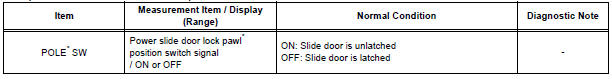
* "POLE" appears on the display of the intelligent tester, however the name of the part corresponding to the display of the tester is "pawl".
26 INSPECT POWER SLIDE DOOR LOCK ASSEMBLY LH
27 CHECK WIRE HARNESS (POWER SLIDE DOOR LOCK ASSEMBLY LH - POWER SLIDE DOOR ECU LH)
REPLACE POWER SLIDE DOOR ECU LH
28 PERFORM ACTIVE TEST BY INTELLIGENT TESTER
- Select the ACTIVE TEST and then check that the slide door lock release motor LH operates.
HINT: During the ACTIVE TEST, the intelligent tester sends a signal to the power slide door ECU LH to drive the release motor. If the release motor operates, the release motor itself and the wire harness between the release motor and power slide ECU LH are considered to be functioning normally.
OK (Power slide door ECU LH):

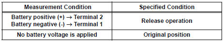
29 INSPECT SLIDE DOOR LOCK RELEASE MOTOR ASSEMBLY
- Apply battery voltage and inspect operation of the release motor.
OK
30 CHECK WIRE HARNESS (SLIDE DOOR LOCK RELEASE MOTOR LH - POWER SLIDE DOOR ECU LH)
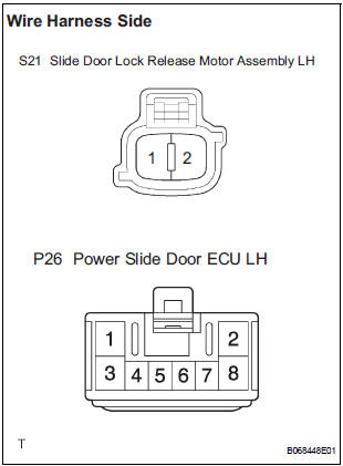
- Disconnect the S21 motor and P26 ECU connectors.
- Check the resistance between the wire harness side connectors.
Resistance (Check for open circuit)
- Check the resistance between the S21 motor connector and body ground.
Resistance (Check for open circuit)
31 REPLACE POWER SLIDE DOOR ECU LH
- Check the power slide door for normal OPEN / CLOSE operation.
SYSTEM NORMAL
 Power Slide Door LH does not Operate When Satellite Switch is
Pressed
Power Slide Door LH does not Operate When Satellite Switch is
Pressed
DESCRIPTION
The power slide door operates only when the power slide door main
switch is ON (switch free: orange
paint on the top of the switch appears). The power slide door ECU LH
c ...
 Power Slide Door RH does not Operate When Satellite Switch is
Pressed
Power Slide Door RH does not Operate When Satellite Switch is
Pressed
DESCRIPTION
The power slide door operates only when the power slide door main
switch is ON (switch free: orange
paint on the top of the switch appears). The power slide door ECU RH
c ...
Other materials:
Shifting the shift lever
While the engine switch is in the
“ON” position (vehicles without a
smart key system) or IGNITION ON mode (vehicles with a smart
key system), move the shift lever with the brake pedal
depressed.
When shifting the shift lever between P and D, make sure that the vehicle
is completely ...
Stuck in Deceleration Sensor
DESCRIPTION
The yaw rate sensor and deceleration sensor signal is sent to the skid
control ECU through the CAN
communication system. When there is a malfunction in the communication, it will
be detected by the
diagnosis function.
WIRING DIAGRAM
INSPECTION PROCEDURE
HINT:
When ...
Stereo Component Amplifier Communication Error
INSPECTION PROCEDURE
1 IDENTIFY THE COMPONENT SHOWN BY THE SUB-CODE
Enter the diagnostic mode.
Press the "LAN Mon" switch to change to "LAN Monitor"
mode.
Identify the component shown by the sub-code.
HINT:
"110 (multi-display)" i ...
