Toyota Sienna Service Manual: Rear axle hub bolt
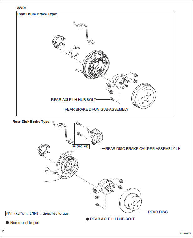
COMPONENTS
Replacement
HINT: Replace the RH side using the same procedures as for the LH side.
1. REMOVE REAR WHEEL
2. SEPARATE REAR DISC BRAKE CALIPER ASSEMBLY LH
(a) Separate rear disc brake caliper assembly LH for 2WD and disk rear brake type (See page AH-16).
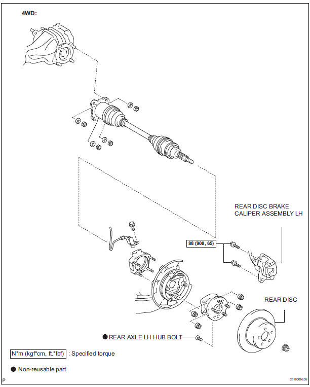
3. SEPARATE REAR DISC BRAKE CALIPER ASSEMBLY LH
(a) Separate rear disc brake caliper assembly LH for 4WD and disk rear brake type (See page AH-19).
4. REMOVE REAR DISC
(a) Remove rear disc for disk rear brake type.
5. REMOVE REAR BRAKE DRUM SUB-ASSEMBLY
(a) Remove rear brake drum sub-assembly for drum rear brake type.
6. REMOVE REAR AXLE LH HUB BOLT
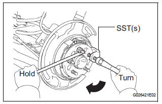
(a) Temporarily install the 2 nuts and washers to the rear axle LH hub bolt as shown in the illustration.
(b) Using SST(s) and a hammer handle or an equivalent to hold the hub & bearing assembly, remove the rear axle LH hub bolt.
SST 09628-10011
7. INSTALL REAR AXLE LH HUB BOLT
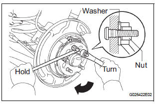
(a) Install a washer and nut to a new bolt, as shown in the illustration.
(b) Using a hammer handle or an equivalent to hold the hub & bearing assembly, install the rear axle LH hub bolt by tightening the nut.
8. INSTALL REAR DISC
(a) Install rear disc for disk rear brake type.
9. INSTALL REAR DISC BRAKE CALIPER ASSEMBLY LH
(a) Install rear disc brake caliper assembly LH for 2WD and disk rear brake type (See page AH-17).
10. INSTALL REAR DISC BRAKE CALIPER ASSEMBLY LH
(a) Install rear disc brake caliper assembly LH for 4WD and disk rear brake type (See page AH-20).
11. INSTALL REAR BRAKE DRUM SUB-ASSEMBLY
(a) Install rear brake drum sub-assembly for drum rear brake type.
12. INSTALL REAR WHEEL Torque: 103 N*m (1,050 kgf*cm, 76 ft.*lbf)
 Installation
1. INSTALL FRONT AXLE ASSEMBLY LH
(a) Install the 2 bolts, nuts and front axle assembly LH
with the 2 bolts and nuts to the shock absorber
assembly front LH.
Torque: 230 N*m (2,350 kgf*cm, 170 ...
 Rear axle hub and bearing (for 2wd)
COMPONENTS
...
Other materials:
Perform monitor drive pattern
The monitor results and test values can be checked with
the OBD II scan tool or the intelligent tester. The engine
control module (ECM) monitors the emissions-related
components such as the thermostat, catalyst converter
and evaporative emissions (EVAP), and determines
whether they are function ...
Installation
1. INSTALL NAVIGATION ANTENNA ASSEMBLY
2. INSTALL INSTRUMENT PANEL SAFETY PAD SUBASSEMBLY
Using a torque wrench, install the bolt <B>.
Torque: 20 N*m (204 kgf*cm, 14 ft.*lbf)
3. INSTALL SHIFT LEVER ASSEMBLY
Using a torque wrench, install the 4 bolts.
Torque ...
Camera Picture Error
DTC 5C-40 Camera Picture Error
DESCRIPTION
DTC No.
DTC Detection Condition
Trouble Area
5C-40
Synchronous signal from the camera cannot be
transmitted.
Wire harness
Television camera assembly
Radio and navigation assembly
...
