Toyota Sienna Service Manual: Installation
1. INSTALL STABILIZER BAR FRONT
2. INSTALL FRONT STABILIZER BAR BUSH NO.1
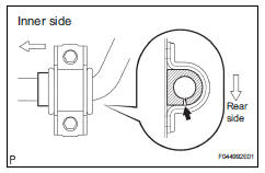
(a) Install the front stabilizer bar bush No. 1.
HINT: Install the bushing to the outer side of the bushing stopper on the stabilizer bar as shown in the illustration.
4. INSTALL RACK & PINION POWER STEERING GEAR ASSEMBLY
HINT: (See page PS-21)
5. CONNECT PRESSURE FEED TUBE ASSEMBLY
HINT: (See page PS-21) SST 09023-12701
6. INSTALL TIE ROD ASSEMBLY LH
HINT: (See page AH-4)
7. INSTALL TIE ROD ASSEMBLY RH
HINT: Install the RH side by the same procedures as the LH side.
8. INSTALL FRONT STABILIZER BRACKET NO.1 LH
(a) Install the front stabilizer bracket No.1 LH with the 2 bolts.
Torque: 17 N*m (173 kgf*cm, 12 ft.*lbf)
HINT: If the ball joint turns together with the nut, use a hexagon (6 mm) wrench to hold the stud.
11. INSTALL FRONT STABILIZER LINK ASSEMBLY RH
HINT: Install the RH side by the same procedures as the LH side.
12. INSTALL FRONT WHEELS
Torque: 103 N*m (1,050 kgf*cm, 76 ft.*lbf)
13. INSPECT CENTER FRONT WHEEL
14. INSPECT STEERING WHEEL CENTER POINT
15. ADD POWER STEERING FLUID
16. BLEED POWER STEERING FLUID
HINT: (See page SP-26)
17. CHECK POWER STEERING FLUID LEAKAGE
18. INSPECT AND ADJUST FRONT WHEEL ALIGNMENT
HINT: (See page SP-4)
 Inspection
1. INSPECT FRONT STABILIZER LINK ASSEMBLY LH
(a) As shown in the illustration, flip the ball joint stud
back and forth 5 times, before installing the nut.
(b) Using a torque wrench, turn the ...
 Front stabilizer bar (for 4wd)
COMPONENTS
...
Other materials:
Illumination Circuit
DESCRIPTION
The Multiplex network body ECU controls illumination light as shown in the
chart below.
Room light assembly (Interior light, luggage component light) and
courtesy light with DOOR position
Map light assembly (Personal light)
Transponder key amplifier (Ignition ke ...
Displaying a Bluetooth®
device details
You can confirm and change the registered device details.
Bluetooth® device registration status
Display the “Bluetooth* Setup” screen.
*: Bluetooth is a registered trademark of Bluetooth SIG, Inc.
Select the device.
Select “Device Info”.
Following screen is displayed:
...
Diagnosis system
1. DESCRIPTION
(a) Release the parking brake pedal.
(b) Check the warning lights.
When ignition switch is turned ON, check that the
ABS warning light and brake warning light come on
for 3 seconds.
HINT:
When parking brake is applied or the level of the
brake fluid is low, the bra ...
