Toyota Sienna Service Manual: Installation
1. INSTALL REAR COIL SPRING INSULATOR UPPER LH
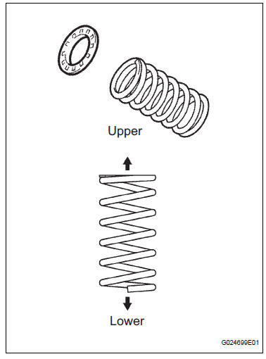
(a) Install the insulator upper LH to the coil spring rear LH.
2. INSTALL COIL SPRING REAR LH
(a) Apply a shop rug to the rear axle beam assembly.
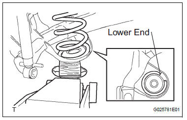
(b) Install the coil spring rear LH to the rear axle beam assembly.
HINT: Fit the lower end of the coil spring into the gap of the spring lower seat.
(c) Apply a shop rug to the rear axle beam assembly.
3. CONNECT SHOCK ABSORBER ASSEMBLY REAR LH
(a) While raising the jack, connect the shock absorber assembly rear LH to the rear axle beam assembly.
(b) Temporarily tighten the nut.
4. CONNECT SHOCK ABSORBER ASSEMBLY REAR RH
HINT: Connect the RH side by the same procedures as the LH side.
5. CONNECT REAR BRAKE TUBE NO.2
(a) Install the flexible hose and clip.
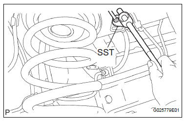
(b) Using SST, connect the brake tube to the flexible hose.
Torque: 15 N*m (153 kgf*cm, 11 ft.*lbf) SST 09023-00101
(c) Install the bolt.
Torque: 8.0 N*m (82 kgf*cm, 71 in.*lbf)
6. CONNECT REAR BRAKE TUBE NO.1 SST 09023-00101
HINT: Connect the RH side by the same procedures as the LH side.
7. INSTALL PARKING BRAKE CABLE ASSEMBLY NO.3
(a) Install the 2 bolts and parking brake cable assembly No.3 to the rear axle beam assembly.
Torque: 8.0 N*m (82 kgf*cm, 71 in.*lbf)
8. INSTALL PARKING BRAKE CABLE ASSEMBLY NO.2
HINT: Install the RH side by same procedures as the LH side.
9. INSTALL DIFFERENTIAL CARRIER ASSEMBLY REAR (for 4WD)
HINT: (See page DF-8)
10. INSTALL REAR DRIVE SHAFT ASSEMBLY LH (for 4WD)
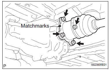
(a) Install the rear drive shaft assembly LH, 4 washers and 4 nuts.
Torque: 56 N*m (571 kgf*cm, 41 ft.*lbf)
11. INSTALL REAR DRIVE SHAFT ASSEMBLY RH (for 4WD)
HINT: Install the RH side by same procedures as the LH side.
12. INSTALL PROPELLER W/CENTER BEARING SHAFT ASSEMBLY (for 4WD)
HINT: (See page PR-2)
13. INSTALL SPEED SENSOR REAR LH (for 4WD)
(a) Install the speed sensor rear LH and bolt.
Torque: 8.0 N*m (82 kgf*cm, 71 in.*lbf)
14. INSTALL SPEED SENSOR REAR RH (for 4WD)
HINT: Install the RH side by same procedures as the LH side.
15. CONNECT SKID CONTROL SENSOR WIRE (for 2WD)
(a) Connect the skid control sensor connector.
(b) Install the bolt and bracket to the rear axle beam assembly.
Torque: 8.0 N*m (82 kgf*cm, 71 in.*lbf)
HINT: Connect the RH side by same procedures with the LH side.
16. INSTALL EXHAUST PIPE ASSEMBLY TAIL
HINT:
- 2WD DRIVE TYPE (See page EX-2)
- 4WD DRIVE TYPE (See page EX-12)
17. BLEED BRAKE LINE
18. INSPECT BRAKE FLUID LEVEL IN RESERVOIR
19. STABILIZE SUSPENSION
(a) Install the rear wheel and jack down the vehicle.
Torque: 103 N*m (1,050 kgf*cm, 76 ft.*lbf) (b) Bounce the vehicle up and down several times to stabilize the suspension.
20. FULLY TIGHTEN SHOCK ABSORBER ASSEMBLY REAR LH
(a) Stabilize the shock absorber assembly rear LH.
If it is impossible to tighten the nut at this position, support the rear axle beam assembly with a jack and load the rear compartment with a mass of approximately 90 kg (198 lb).
Length of shock absorber: 2WD DRIVE TYPE: 234 mm (9.2 in.) 4WD DRIVE TYPE: 258 mm (10.2 in.)
(b) Fully tighten the nut.
Torque: 115 N*m (1,173 kgf*cm, 85 ft.*lbf)
21. FULLY TIGHTEN SHOCK ABSORBER ASSEMBLY REAR RH
HINT: Fully tighten the RH side by same procedures as the LH side.
22. FULLY TIGHTEN REAR AXLE BEAM ASSEMBLY
(a) Stabilize the rear axle beam assembly.
(b) Fully tighten the bolt.
Torque: 135 N*m (1,377 kgf*cm, 100 ft.*lbf)
NOTICE:
- Tighten the bolt and not the nut.
- The vehicle height should be the same as the height that the shock absorber is fully tightened.
HINT: Fully tighten the RH side by same procedures as the LH side.
23. INSTALL REAR FLOOR NO.2 CROSSMEMBER BRACE LH
(a) Install the floor No.2 crossmember brace and 2 bolts.
Torque: 28 N*m (286 kgf*cm, 21 ft.*lbf)
24. INSTALL REAR FLOOR NO.2 CROSSMEMBER BRACE RH
HINT: Install the RH side by the same procedures as the LH side.
25. INSTALL FUEL TANK FILLER HOSE COVER
(a) Install the fuel tank filler pipe protector, 2 bolts, 3 screws and 3 nuts.
(b) Install the fuel tank filler hose cover and 3 bolts.
Torque: 5.0 N*m (51 kgf*cm, 44 in.*lbf)
26. INSPECT REAR WHEEL ALIGNMENT
HINT: (See page SP-9)
27. CHECK ABS SPEED SENSOR SIGNAL
(a) ABS WITH EBD SYSTEM (See page BC-2) (b) ABS WITH EBD & BA & TRAC & VSC SYSTEM (See page BC-68)
 Removal
1. REMOVE REAR WHEEL
2. REMOVE SKID CONTROL SENSOR WIRE (for 2WD)
(a) Disconnect the skid control sensor connector.
(b) Remove the bolt and disconnect the bracket from
the rear axle beam assembl ...
 Rear shock absorber
COMPONENTS
...
Other materials:
Removal
HINT:
On the RH side, use the same procedures as on the LH side.
1. REMOVE SLIDE DOOR
Remove the rear door scuff plate (See page IR-7).
Remove the back door scuff plate (See page ED-
214).
Remove the quarter trim panel (See page IR-9).
Remove the upper rail cushion from the rail.
...
Installation
1. INSTALL NO. 2 REAR SEAT OUTER BELT ASSEMBLY
NOTICE:
Do not disassemble the retractor.
Check the degree of tilt when the No. 2 rear seat
outer belt assembly begins to lock the ELR.
Check that the belt does not lock within 15 of
tilt in all directions but that the be ...
Front washer motor
ON-VEHICLE INSPECTION
1. INSPECT FRONT WASHER MOTOR
Operation Check
Pour the water into the washer jar with the
windshield washer motor and pump installed to
the washer jar assembly.
Connect the battery (+) to the terminal 1 of the
windshield washer motor and ...
