Toyota Sienna Service Manual: Removal
1. REMOVE REAR WHEEL
2. REMOVE SKID CONTROL SENSOR WIRE (for 2WD)
(a) Disconnect the skid control sensor connector.
(b) Remove the bolt and disconnect the bracket from the rear axle beam assembly.
HINT: Separate the RH side by the same procedures as the LH side.
3. SEPARATE SPEED SENSOR REAR LH (for 4WD)
(a) Remove the bolt and speed sensor rear LH.
4. SEPARATE SPEED SENSOR REAR RH (for 4WD)
HINT: Separate the RH side by the same procedures as the LH side.
5. REMOVE EXHAUST PIPE ASSEMBLY TAIL
HINT:
- 2WD DRIVE TYPE (See page EX-2)
- 4WD DRIVE TYPE (See page EX-8)
6. REMOVE PROPELLER W/CENTER BEARING SHAFT ASSEMBLY (for 4WD)
HINT: (See page PR-2)
7. SEPARATE REAR DRIVE SHAFT ASSEMBLY LH (for 4WD)

(a) Place matchmarks on the rear drive shaft assembly LH and differential flange.
(b) Remove the 4 nuts and 4 washers, separate rear drive shaft assembly LH.
8. SEPARATE REAR DRIVE SHAFT ASSEMBLY RH (for 4WD)
HINT: Separate the RH side by the same procedures as the LH side.
9. REMOVE DIFFERENTIAL CARRIER ASSEMBLY REAR (for 4WD)
HINT: (See page DF-8)
10. SEPARATE PARKING BRAKE CABLE ASSEMBLY NO.3
(a) Remove the 2 bolts and parking brake cable assembly No.3.
11. SEPARATE PARKING BRAKE CABLE ASSEMBLY NO.2
HINT: Separate the RH side by the same procedures as the LH side.
12. SEPARATE REAR BRAKE TUBE NO.2
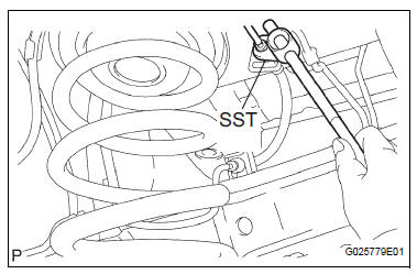
(a) Using SST, separate the brake tube from the flexible hose. Catch the brake fluid with a container as it drains out.
SST 09023-00101
(b) Remove the clip, and separate the flexible hose.
(c) Remove the bolt and separate the brake tube from rear axle beam assembly.
13. SEPARATE REAR BRAKE TUBE NO.1
SST 09023-00101
HINT: Separate the RH side by the same procedures as the LH side.
14. REMOVE FUEL TANK FILLER HOSE COVER
(a) Remove the 2 bolts, 3 screws, 3 nuts and fuel tank filler pipe protector.
(b) Remove the 3 bolts and fuel tank filler hose cover.
15. REMOVE REAR FLOOR NO.2 CROSSMEMBER BRACE LH
(a) Remove the 2 bolts and floor No.2 crossmember brace.
16. REMOVE REAR FLOOR NO.2 CROSSMEMBER BRACE RH
HINT: Remove the RH side by the same procedures as the LH side.
17. LOOSEN REAR AXLE BEAM ASSEMBLY
(a) Refer to hint below.
HINT: Loosen the RH side by the same procedures as the LH side.
NOTICE:
- When loosening the bolt, hold the nut not to rotate.
- Do not remove the bolt and nut.
18. SEPARATE SHOCK ABSORBER ASSEMBLY REAR LH
(a) Support the rear axle beam assembly with a jack.
(b) Remove the bolt and separate the shock absorber assembly rear LH.
19. SEPARATE SHOCK ABSORBER ASSEMBLY REAR RH
HINT: Separate the RH side by the same procedures as the LH side.
20. REMOVE COIL SPRING REAR LH
(a) Apply a shop rug between the coil spring rear LH and rear axle beam assembly.
(b) Apply a shop rug between the coil spring rear RH and rear axle beam assembly.
(c) Remove the coil spring LH by slowly lowering the jack.
21. REMOVE REAR COIL SPRING INSULATOR UPPER LH
(a) Remove the rear coil spring insulator upper LH from the coil spring rear LH.
 Rear coil spring
COMPONENTS
...
 Installation
1. INSTALL REAR COIL SPRING INSULATOR UPPER LH
(a) Install the insulator upper LH to the coil spring rear
LH.
2. INSTALL COIL SPRING REAR LH
(a) Apply a shop rug to the rear axle beam asse ...
Other materials:
Open in Occupant Classification ECU Battery
Positive Line
DTC B1794 Open in Occupant Classification ECU Battery
Positive Line
DESCRIPTION
This circuit consists of the occupant classification ECU and the power source
circuit (battery, fuse, wire
harness).
DTC B1794 is recorded when a malfunction is detected in the occupant
classification ECU or t ...
Initialization
Items to initialize
The following items must be initialized for normal system operation
after such cases as the battery being reconnected, or maintenance
being performed on the vehicle.
Item
When to initialize
Power sliding door
(if equipped)
After reconnecting o ...
Unlocking and locking the doors from the inside
Door lock switch
Locks all the doors
Unlocks all the doors
Inside lock button
Locks the door
Unlocks the door
The front doors can be opened
by pulling the inside handle
even if the lock buttons are in
the lock position. ...
