Toyota Sienna Service Manual: Installation
1. INSTALL BRAKE ACTUATOR
NOTICE: Do not remove the hole plugs before connecting the brake tubes. New actuators are filled with brake fluid.
(a) Install the brake actuator assembly with the 2 nuts.
Torque: 5.4 N*m (55 kgf*cm, 48 in.*lbf)
2. INSTALL BRAKE ACTUATOR WITH BRACKET
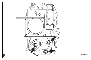
(a) Install the actuator with bracket with the 3 bolts.
Torque: 20 N*m (199 kgf*cm, 14 ft.*lbf)
NOTICE: Be careful not to damage the brake tubes and wire harness.
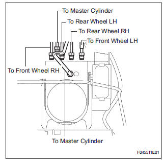
(b) Using SST, connect each brake tube to correct positions of the actuator with bracket, as shown in the illustration.
Torque: 15 N*m (155 kgf*cm, 11 ft.*lbf)
(c) Connect the brake actuator connector.
3. INSTALL AIR CLEANER ASSEMBLY WITH HOSE
4. FILL RESERVOIR WITH BRAKE FLUID (See page BR- 3)
5. BLEED BRAKE MASTER CYLINDER SUBASSEMBLY (See page BR-3)
6. BLEED BRAKE LINE (See page BR-4)
7. BLEED BRAKE ACTUATOR (See page BR-4)
8. CHECK BRAKE FLUID LEAKAGE
9. CHECK FLUID LEVEL IN RESERVOIR (See page BR- 7)
10. CONNECT BATTERY NEGATIVE TERMINAL
11. PERFORM INITIALIZATION
12. PERFORM YAW RATE SENSOR ZERO POINT CALIBRATION
HINT: See page BC-70.
13. CHECK BRAKE ACTUATOR WITH INTELLIGENT TESTER
HINT: See page BC-178.
 Removal
1. DRAIN BRAKE FLUID
NOTICE:
Wash brake fluid off immediately if it adheres to any
painted surface.
2. DISCONNECT BATTERY NEGATIVE TERMINAL
3. REMOVE AIR CLEANER ASSEMBLY WITH HOSE
4. REMOVE BRA ...
 Brake actuator (w/o vsc)
Components
...
Other materials:
ABS Control System Malfunction
DTC 43 ABS Control System Malfunction
DESCRIPTION
This DTC is output when the VSC system detects a malfunction in the ABS
control system.
INSPECTION PROCEDURE
NOTICE:
When replacing the brake actuator assembly, perform zero point calibration
(See page BC-70).
1 CHECK ABS CONTROL SYSTEM
( ...
Insufficient Coolant Temperature for Closed Loop Fuel Control
DESCRIPTION
Refer to DTC P0115 (See page ES-133).
MONITOR DESCRIPTION
The resistance of the ECT sensor varies in proportion to the actual ECT. The
ECM supplies a constant
voltage to the sensor and monitors the signal output voltage of the sensor. The
signal voltage output
varies acc ...
Communication Error from Distance Control
ECU to ECM
DTC P1615 Communication Error from Distance Control
ECU to ECM
DTC U1101 Lost Communication with Distance Control
ECU
DESCRIPTION
The distance control ECU receives information about the area in front of the
vehicle from the laser sensor
and then sends a brake control demand signal (decelerat ...
