Toyota Sienna Service Manual: Removal
1. DRAIN BRAKE FLUID
NOTICE: Wash brake fluid off immediately if it adheres to any painted surface.
2. DISCONNECT BATTERY NEGATIVE TERMINAL
3. REMOVE AIR CLEANER ASSEMBLY WITH HOSE
4. REMOVE BRAKE ACTUATOR WITH BRACKET
(a) Release the latch of the brake actuator connector to disconnect the connector.
(b) Using SST, disconnect the 6 brake tubes from the actuator with bracket.
SST 09023-00101
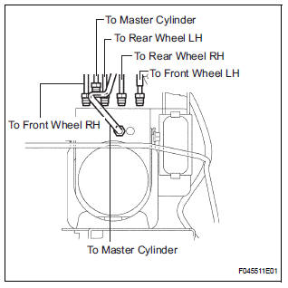
(c) Use tags or make a memo to identify the places to reconnect.
(d) Remove the 3 bolts and the actuator with bracket.
NOTICE: Be careful not to damage the brake tubes and wire harness.
5. REMOVE BRAKE ACTUATOR
(a) Remove the 2 nuts and the brake actuator assembly from the brake actuator bracket.
 On-vehicle inspection
1. CONNECT INTELLIGENT TESTER
(a) Connect the intelligent tester to the DLC3.
(b) Start the engine and run at idle.
(c) Select the ACTIVE TEST mode on the intelligent
tester.
HINT:
Pleas ...
 Installation
1. INSTALL BRAKE ACTUATOR
NOTICE:
Do not remove the hole plugs before connecting the
brake tubes. New actuators are filled with brake
fluid.
(a) Install the brake actuator assembly with the 2 nut ...
Other materials:
On-vehicle inspection
1. INSPECT SPEEDOMETER
Check the operation.
Using a speedometer tester, check the
speedometer indication according to the table
below.
Reference: mph (U.S.A.)
Reference: km/h (Canada)
NOTICE:
Tire wear as well as over or under inflation
will cause errors.
...
If the vehicle becomes
stuck
Carry out the following procedures if the tires spin or the vehicle
becomes stuck in mud, dirt, or snow:
Stop the engine. Set the parking brake and shift the shift lever to P.
Remove the mud, snow, or sand from around the stuck tire.
Place wood, stones or some other material under the tires ...
Terminals of ECU
1. JUNCTION CONNECTOR
Junction connector
with VSC
HINT:
*1: with Dynamic laser cruise control
without VSC
CAN junction connector (with VSC)
with VSC
The connection diagram of the components which
are connected to the CAN junction connector.
2. DLC3
...
