Toyota Sienna Service Manual: Installation
1. INSTALL BRAKE ACTUATOR
(a) Install the brake actuator assembly with the 2 nuts.
Torque: 5.4 N*m (55 kgf*cm, 48 in.*lbf)
2. INSTALL BRAKE ACTUATOR WITH BRACKET
(a) Install the actuator with bracket with the 3 bolts.
Torque: 20 N*m (199 kgf*cm, 14 ft.*lbf)
NOTICE: Be careful not to damage the brake tubes and wire harness.
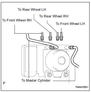
(b) Using SST, connect each brake tube to correct positions of the actuator with bracket, as shown in the illustration.
Torque: 15 N*m (155 kgf*cm, 11 ft.*lbf)
(c) Connect the brake actuator connector assembly.
3. INSTALL AIR CLEANER ASSEMBLY WITH HOSE
4. FILL RESERVOIR WITH BRAKE FLUID (See page BR- 3)
5. BLEED BRAKE MASTER CYLINDER SUBASSEMBLY (See page BR-3)
6. BLEED BRAKE LINE (See page BR-4)
7. CHECK BRAKE FLUID LEAKAGE
8. CHECK FLUID LEVEL IN RESERVOIR (See page BR- 7)
9. CONNECT BATTERY NEGATIVE TERMINAL
10. PERFORM INITIALIZATION
11. CHECK BRAKE ACTUATOR WITH INTELLIGENT TESTER
HINT: See page BC-183.
 Removal
1. DRAIN BRAKE FLUID
NOTICE:
Wash brake fluid off immediately if it adheres to any
painted surface.
2. DISCONNECT BATTERY NEGATIVE TERMINAL
3. REMOVE AIR CLEANER ASSEMBLY WITH HOSE
4. REMOVE BRA ...
 Front speed sensor
Components
...
Other materials:
On-vehicle inspection
1. INSPECT FOR FUEL PUMP OPERATION AND FUEL
LEAK
(a) Check fuel pump operation.
(1) Connect the intelligent tester to the DLC3.
(2) Turn the engine switch on (IG) and push the
intelligent tester main switch on.
NOTICE:
Do not start the engine.
(3) Select the following menu it ...
Inspection
1. INSPECT POWER STEERING RACK
(a) Using a dial indicator, check the power steering rack
for runout and for teeth wear and damage.
Maximum runout:
0.3 mm (0.012 in.)
If necessary, replace the rack & pinion power
steering gear assembly.
(b) Check the back surface for wear and damag ...
Mass or Volume Air Flow Circuit Range / Performance Problem
DESCRIPTION
Refer to DTC P0100 (See page ES-116).
MONITOR DESCRIPTION
The MAF meter is a sensor that measures the amount of air flowing through the
throttle valve. The ECM
uses this information to determine the fuel injection time and to provide an
appropriate air-fuel ratio.
Insi ...
