Toyota Sienna Service Manual: Sound Signal Circuit between Video Terminal and Television Display
DESCRIPTION
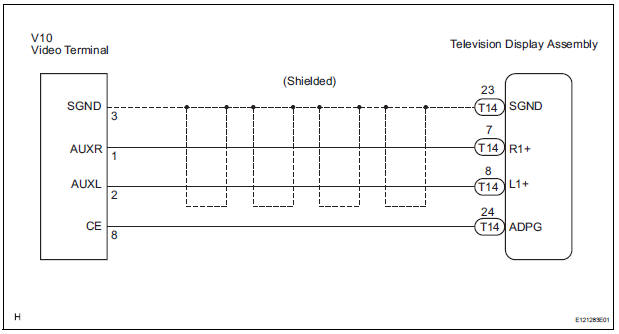
This is the sound signal circuit from the video (video adapter) terminal to the television display assembly.
WIRING DIAGRAM
INSPECTION PROCEDURE
1 CHECK HARNESS AND CONNECTOR (TELEVISION DISPLAY ASSEMBLY - VIDEO TERMINAL)
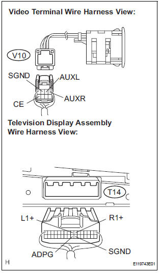
- Disconnect the connectors from the video (video adapter) terminal and television display assembly.
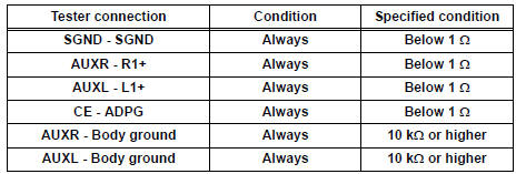
- Measure the resistance according to the value(s) in the table below.
Standard resistance
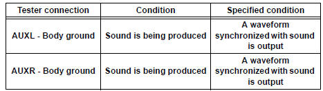
2 INSPECT VIDEO TERMINAL
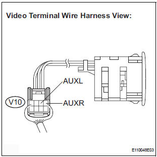
- Reconnect the video (video adapter) terminal connector.
- Using an oscilloscope, check the signal waveform between each terminal and body ground according to the conditions, as shown in the chart.
HINT: An external device system is playing (When the video (video adapter) terminal is used).
Signal waveform
PROCEED TO NEXT CIRCUIT INSPECTION SHOWN IN PROBLEM SYMPTOMS TABLE
 A Remote Control System does not Operate
INSPECTION PROCEDURE
1 CHECK SYSTEM
Check that the remote control operation of the rear
system is not locked by the radio receiver or the radio
and navigation assembly.
Check ...
 Display Signal Circuit between Video Terminal and Television Display
DESCRIPTION
This is the display signal circuit from the video terminal to the television
display assembly.
WIRING DIAGRAM
INSPECTION PROCEDURE
1 CHECK HARNESS AND CONNECTOR (TELEVISION DISPL ...
Other materials:
Hood
Release the lock from the inside of the vehicle to open the hood.
Pull the hood lock release lever.
The hood will pop up slightly.
Pull up the auxiliary catch lever
and lift the hood.
Hold the hood open by inserting
the supporting rod into the slot
WARNING ...
Only Wireless Door Lock Control Function does not Operate
DESCRIPTION
The door control receiver receives a signal from the transmitter and sends
this signal to the multiplex
network body ECU. Then, the multiplex network body ECU controls operation of the
door locks and power
windows.
Then, the power slide door ECU causes the power slide door to o ...
DSP Error
DTC 63-78 DSP Error
DESCRIPTION
DTC No.
DTC Detection Condition
Trouble Area
63-78
An error occurs during the decode process (MP3 /
WMA).
-
INSPECTION PROCEDURE
HINT:
After the inspection completed, clear the DTCs.
NOTICE:
This ...
