Toyota Sienna Service Manual: Removal
1. DRAIN BRAKE FLUID
NOTICE: Wash brake fluid off immediately if it adheres to any painted surface.
2. DISCONNECT BATTERY NEGATIVE TERMINAL
3. REMOVE AIR CLEANER ASSEMBLY WITH HOSE
4. REMOVE BRAKE ACTUATOR WITH BRACKET
(a) Release the latch of the brake actuator connector to disconnect the connector (b) Using SST, disconnect the 6 brake tubes from the actuator with bracket.
SST 09023-00101
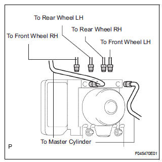
(c) Use tags or make a memo to identify the places to reconnect.
(d) Remove the 3 bolts and the actuator with bracket.
NOTICE: Be careful not to damage the brake tubes and wire harness.
5. REMOVE BRAKE ACTUATOR
(a) Remove the 2 nuts and the brake actuator assembly from the brake actuator bracket.
 On-vehicle inspection
1. CONNECT INTELLIGENT TESTER
(a) Connect the intelligent tester to the DLC3.
(b) Start the engine and run at idle.
(c) Select the ACTIVE TEST mode on the intelligent
tester.
HINT:
Pleas ...
 Installation
1. INSTALL BRAKE ACTUATOR
(a) Install the brake actuator assembly with the 2 nuts.
Torque: 5.4 N*m (55 kgf*cm, 48 in.*lbf)
2. INSTALL BRAKE ACTUATOR WITH BRACKET
(a) Install the actuator wit ...
Other materials:
Distance Control Switch Circuit
DESCRIPTION
The distance control switch sets the vehicle-to-vehicle distance mode. The
distance control switch is
installed in the steering pad switch. The vehicle-to-vehicle distance set value
can be changed by
operating the steering pad switch (distance control switch) while the dynamic
l ...
Sensor detection display, obstacle distance
Distance display
Sensors that detect an obstacle will illuminate continuously or blink.
*1: The images may differ from that shown in the illustrations.
*2: Multi-information display
*3: Audio system screen
Buzzer operation and distance to an obstacle
A buzzer sounds when the sensors are o ...
Installation
1. INSTALL SEAT POSITION AIRBAG SENSOR
Check that the ignition switch is off.
Check that the negative battery (-) terminal is
disconnected.
CAUTION:
After disconnecting the negative battery
terminal, wait for at least 90 seconds before
starting the operation.
...
