
Toyota Sienna Service Manual: Installation
1. INSTALL STEERING ANGLE SENSOR
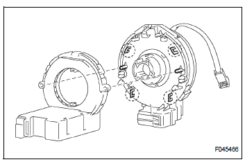
(a) Install the steering sensor onto the spiral cable.
2. PLACE FRONT WHEELS FACING STRAIGHT AHEAD
3. INSTALL SPIRAL CABLE SUB-ASSEMBLY (See page RS-434)
4. INSTALL STEERING COLUMN COVER LWR (See page RS-435)
5. CENTER SPIRAL CABLE (See page RS-435)
6. INSTALL STEERING WHEEL ASSEMBLY
7. INSPECT STEERING WHEEL CENTER POINT (See page SR-11)
8. INSTALL HORN BUTTON ASSEMBLY (See page RS- 424)
9. INSPECT SRS WARNING LIGHT
HINT: See page RS-1.
 Removal
1. PRECAUTION
HINT:
See page RS-1
2. SEPARATE BATTERY NEGATIVE TERMINAL
3. PLACE FRONT WHEELS FACING STRAIGHT AHEAD
4. REMOVE HORN BUTTON ASSEMBLY (See page RS-
424)
5. REMOVE STEERING WHEEL AS ...
 Brake system
...
Other materials:
Disposal
HINT:
Use the same procedures for the RH side and LH side.
The procedures listed below are for the LH side.
When scrapping a vehicle equipped with the SRS or
disposing of the curtain shield airbag assembly, be sure to
deploy the airbag first in accordance with the procedure
described b ...
Short in Driver Side Squib 2nd Step Circuit
DTC B1180/17 Short in Driver Side Squib 2nd Step Circuit
DESCRIPTION
The driver side squib 2nd step circuit consists of the center airbag sensor
assembly, the spiral cable and
the steering pad.
The circuit instructs the SRS to deploy when deployment conditions are met.
DTC B1180/17 is rec ...
System diagram
1. DISC PLAYER OUTLINE
A CD player uses a laser pickup to read digital
signals recorded on CDs. By converting the digital
signals to analog, music and other content can be
played.
CAUTION:
Do not look directly at the laser pickup because
the CD player uses an invisible laser bea ...
