Toyota Sienna Service Manual: Installation
1. INSTALL BRAKE PEDAL SUPPORT ASSEMBLY
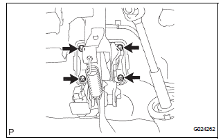
(a) Install the brake pedal support sub-assembly with the 4 nuts.
Torque: 16 N*m (160 kgf*cm, 12 ft.*lbf) (b) Install the clip and clevis pin to the brake pedal lever.
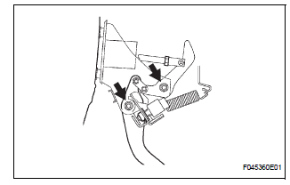
(c) Using needle-nose pliers, install the tension spring.
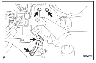
(d) Install the 2 bolts to the brake pedal bracket No. 3.
Torque: 19 N*m (194 kgf*cm, 14 ft.*lbf) (e) Install the stop light switch harness clamp to the brake pedal support sub-assembly.
(f) Connect the stop light switch connector.
2. FULLY TIGHTEN BRAKE PEDAL SHAFT
(a) Fully tighten the 2 brake pedal shafts.
Torque: 34 N*m (350 kgf*cm, 25 ft.*lbf)
3. INSTALL INSTRUMENT PANEL SAFETY PAD INSERT SUB-ASSEMBLY NO. 1
(a) Install the instrument panel safety pad insert subassembly No. 1 with the 4 bolts.
4. INSTALL INSTRUMENT PANEL FINISH PANEL SUBASSEMBLY LOWER LH
(a) Install the instrument panel finish panel subassembly lower LH with the 2 bolts.
5. INSTALL COWL SIDE TRIM BOARD LH
6. INSTALL FRONT DOOR SCUFF PLATE LH
7. INSPECT BRAKE PEDAL HEIGHT (See page BR-9)
8. CHECK PEDAL FREE PLAY (See page BR-10)
9. CHECK PEDAL RESERVE DISTANCE (See page BR- 10)
 Reassembly
1. INSTALL BRAKE PEDAL PAD
(a) Install the brake pedal pad to the brake pedal subassembly.
2. INSTALL PUSH ROD PIN
(a) Apply lithium soap base glycol grease to inside
surface of 2 new push rod bus ...
 Brake master cylinder
COMPONENTS
...
Other materials:
Driver Side Outer Mirror
DTC B1209 Driver Side Outer Mirror
DESCRIPTION
This DTC is detected when communication between the outer mirror control ECU
LH and multiplex
network gateway ECU stops for more than 10 seconds
DTC No.
DTC Detection Condition
Trouble Area
B1209
Driver sid ...
Front Occupant Classification Sensor RH Collision
Detection
DTC B1786 Front Occupant Classification Sensor RH Collision
Detection
DESCRIPTION
DTC B1786 is output when the occupant classification ECU receives a collision
detection signal sent by
the front occupant classification sensor RH if an accident occurs.
DTC B1786 is also output when the front ...
Precaution
1. PRECAUTION OF HEADLIGHT BULB
REPLACEMENT
When any defects such as deformation, crack, dent,
chipping, etc. are identified on the discharge
headlight (especially, on the light control ECU),
replace it with a new one.
Even if the operation seems to be normal, the failsafe
...
