Toyota Sienna Service Manual: Disassembly
1. REMOVE AIR REFINER ELEMENT
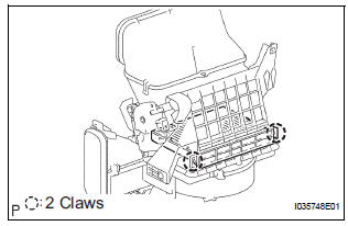
(a) Release the 2 claw fittings and remove the air filter sub-assembly.
(b) Remove the air refiner element from the air filter cover plate.
2. REMOVE COOLING UNIT DAMPER SERVO SUBASSEMBLY
(a) Remove the 3 screws and the cooling unit damper servo sub-assembly.
3. REMOVE BLOWER RESISTOR (for Manual Air Conditioning System)
(a) Remove the 2 screws and the blower resistor.
4. REMOVE BLOWER MOTOR CONTROL (for Automatic Air Conditioning System)
(a) Remove the 2 screws and the blower motor control.
5. REMOVE BLOWER WITH FAN MOTOR SUBASSEMBLY
(a) Remove the 3 screws and the blower w/ fan motor sub-assembly.
 Removal
1. REMOVE INSTRUMENT PANEL SUB-ASSEMBLY WITH PASSENGER AIRBAG ASSEMBLY
HINT:
Refer to the instructions for removal of the instrument
panel sub-assembly w/ passenger airbag assembly (See
page IP-5) ...
 Reassembly
1. INSTALL BLOWER WITH FAN MOTOR SUBASSEMBLY
2. INSTALL BLOWER MOTOR CONTROL (for
Automatic Air Conditioning System)
3. INSTALL BLOWER RESISTOR (for Manual Air
Conditioning System)
4. INSTALL COO ...
Other materials:
Installation
1. INSTALL TIMING CHAIN CASE OIL SEAL
(a) Using SST, tap in a new oil seal until its surface is
flush with the timing chain case edge.
SST 09223-22010, 09506-35010
NOTICE:
Keep the lip free from foreign matter.
Do not tap on the oil seal at an angle.
Make sure that the oil ...
Window defogger switch
INSPECTION
1. INSPECT WINDOW DEFOGGER SWITCH
Check the defogger switch illuminates.
Standard
If the result is not as specified, replace the switch
assembly or bulb.
Check the defogger timer.
Connect the positive (+) lead from the battery
to terminal 2 and ...
Rear wheel alignment
ADJUSTMENT
NOTICE:
For vehicles equipped with VSC, if wheel alignment has
been adjusted, and if suspension or underbody
components have been removed/installed or replaced, be
sure to perform the following initialization procedure in
order for the system to function normally:
1. Disconnect the ...
