Toyota Sienna Service Manual: Installation
HINT:
- Use the same procedures for the RH side and LH side.
- The procedures listed below are for the LH side.
1. INSTALL CURTAIN SHIELD AIRBAG ASSEMBLY LH
- Install the curtain shield airbag assembly LH with the 13 bolts in the order shown in the illustration.
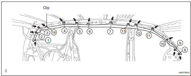
Torque: 14 N*m (143 kgf*cm, 10 ft.*lbf)
NOTICE: Do not twist the curtain shield airbag assembly LH when installing it.
- Install the clip.
- Connect the connector to the curtain shield airbag assembly LH.
NOTICE: When handling the airbag connector, take care not to damage the airbag wire harness.
2. INSTALL POWER BACK DOOR UNIT ASSEMBLY
3. INSTALL ROOF HEADLINING ASSEMBLY
HINT: Refer to the procedures from "INSTALL ROOF HEADLINING ASSEMBLY".
4. INSTALL INSTRUMENT PANEL SUB-ASSEMBLY
5. INSPECT STEERING WHEEL CENTER POINT
6. INSTALL STEERING PAD
7. CONNECT CABLE TO NEGATIVE BATTERY TERMINAL
PERFORM INITIALIZATION
- Perform initialization.
HINT: Some systems need initialization when disconnecting the cable from the negative battery terminal.
9. INSPECT SRS WARNING LIGHT
- Inspect the SRS warning light
 Removal
HINT:
Use the same procedures for the RH side and LH side.
The procedures listed below are for the LH side.
1. PRECAUTION
CAUTION: Be sure to read "PRECAUTION" thoroughly bef ...
 Disposal
HINT:
Use the same procedures for the RH side and LH side.
The procedures listed below are for the LH side.
When scrapping a vehicle equipped with the SRS or
disposing of the curtain shield ...
Other materials:
Problem symptoms table
Vehicle stability control system:
TERMINALS OF ECU
1. Terminal of ECU
(*1): Models with dynamic laser cruise control
(*2): 2WD model
2. Terminal Inspection
(a) Disconnect the connector and measure the voltage or resistance on the wire harness side.
HINT: Voltage cannot be measured wit ...
Short to GND in Curtain Shield Squib LH Circuit
DTC B1167/85 Short to GND in Curtain Shield Squib LH Circuit
DESCRIPTION
The curtain shield squib LH circuit consists of the center airbag sensor
assembly and the curtain shield
airbag assembly LH.
The circuit instructs the SRS to deploy when deployment conditions are met.
DTC B1167/85 is ...
Disassembly
1. Remove park/neutral position switch assembly
(A) remove the nut, washer and control shaft lever.
(B) using a screwdriver, unstake the nut stopper, and
remove the lock nut and nut stopper.
(c) Remove the 2 bolts and pull out the park/neutral
position switch.
2. REMOVE BREATHER PLUG H ...
