Toyota Sienna Service Manual: Installation
1. INSTALL CENTER AIRBAG SENSOR ASSEMBLY
- Check that the ignition switch is off.
- Check that the battery negative (-) terminal is
disconnected.
CAUTION: After disconnecting the negative battery terminal, wait for at least 90 seconds before starting the operation.
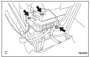
- Temporarily install the center airbag sensor assembly with the 3 bolts.
NOTICE:
- If the center airbag sensor assembly has been dropped, or there are any cracks, dents or other defects in the case, bracket or connector, replace it with a new one.
- When installing the center airbag sensor assembly, be careful that the SRS wiring does not interfere with other parts and that it is not pinched between other parts.
- Tighten the 3 bolts to the specified torque.
Torque: 17.5 N*m (179 kgf*cm, 13 ft.*lbf)
- Check that there is no looseness in the installation parts of the center airbag sensor assembly.
- Connect the 3 connectors to the center airbag sensor assembly.
- Check that the waterproof sheet is properly set.
2. INSTALL AIR DUCT NO.1 REAR
3. INSTALL AIR DUCT NO.3 REAR
4. INSTALL AIR DUCT NO.4 REAR
5. INSTALL INSTRUMENT CLUSTER FINISH PANEL SUB-ASSEMBLY LOWER CENTER
6. INSTALL INSTRUMENT CLUSTER FINISH PANEL ASSEMBLY CENTER
7. INSTALL INSTRUMENT PANEL BOX NO.2
8. INSTALL GLOVE COMPARTMENT DOOR ASSEMBLY
9. INSTALL FLOOR CARPET COVER CENTER LH
10. INSTALL FLOOR CARPET COVER CENTER RH
HINT: Use the same procedures for the floor carpet cover center RH and floor carpet cover center LH.
11. INSTALL INSTRUMENT PANEL FINISH PANEL SUBASSEMBLY LOWER LH
12. CONNECT CABLE TO NEGATIVE BATTERY TERMINAL
13. PERFORM INITIALIZATION
- Perform initialization.
HINT: Some systems need initialization when disconnecting the cable from the negative battery terminal.
14. INSPECT SRS WARNING LIGHT
- Inspect the SRS warning light
 Removal
1. PRECAUTION
CAUTION: Be sure to read "PRECAUTION" thoroughly before
servicing.
2. DISCONNECT CABLE FROM NEGATIVE BATTERY
TERMINAL
CAUTION:
Wait for 90 seconds after disconnecting th ...
 Front airbag sensor
COMPONENTS
...
Other materials:
Installation
1. Install speed sensor (nc sensor)
(a) Coat the O-ring with ATF.
(b) Install the speed sensor with the bolt.
Torque: 11 N*m (115 kgf*cm, 8 ft.*lbf)
HINT:
Make sure to install the same manufacturer's
sensor.
(c) Connect the speed sensor connector.
2. INSTALL SPEED SENSOR (NT SENSOR)
...
Registration
NOTICE:
The Vehicle Identification Number (VIN) must be input
into the replacement ECM.
HINT:
The VIN is a 17-digit alphanumeric vehicle identification
number. The intelligent tester is required to register the VIN.
1. INPUT INSTRUCTIONS
The general VIN input instructions using the
...
Disassembly
1. Remove repair service starter kit
(a) Remove the nut and disconnect the lead wire from
the repair service starter kit.
(b) Remove the 2 screws which are used to secure the
repair service starter kit to the repair service starter
kit.
(c) Remove the repair service starter kit.
( ...
