Toyota Sienna Service Manual: Disassembly
1. Remove repair service starter kit
(a) Remove the nut and disconnect the lead wire from the repair service starter kit.
(b) Remove the 2 screws which are used to secure the repair service starter kit to the repair service starter kit.
(c) Remove the repair service starter kit.
(d) Remove the return spring and the plunger from the repair service starter kit.
2. REMOVE STARTER YOKE ASSEMBLY
(a) Remove the 2 through bolts and pull out the starter yoke together with the starter commutator end frame.
(b) Remove the starter yoke from the starter commutator end frame.
3. REMOVE STARTER ARMATURE PLATE
(a) Remove the starter armature plate from the starter yoke.
4. REMOVE DRIVE HOUSING STARTER BEARING COVER
(a) Using a screwdriver, remove the drive housing starter bearing cover.
5. REMOVE STARTER ARMATURE ASSEMBLY
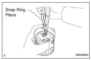
(a) Using snap ring pliers, remove the snap ring and plate washer.
(b) Remove the starter armature from the commutator end frame.
6. REMOVE PLANETARY GEAR
(a) Remove the 3 planetary gears from the repair service starter kit.
 Removal
1. REMOVE BATTERY (See page EM-26)
2. REMOVE NO. 2 AIR CLEANER INLET (See page EM-
28)
3. REMOVE AIR CLEANER CAP SUB-ASSEMBLY (See
page FU-13)
4. REMOVE AIR CLEANER FILTER ELEMENT (See page
EM-2 ...
 Inspection
1. Inspect starter assembly
NOTICE:
These tests must be performed within 3 to 5 seconds
to avoid burning out the coil.
(a) Perform the pull-in test.
(1) Disconnect the lead ...
Other materials:
Engine immobilizer
system
The vehicle’s keys have built-in transponder chips that prevent
the engine from starting if a key has not been previously registered
in the vehicle’s on-board computer.
Never leave the keys inside the vehicle when you leave the vehicle.
This system is designed to help prevent vehicle the ...
Correct use of the seat belts
Make sure that all occupants are wearing their seat belts before driving
the vehicle. Use a child restraint system appropriate for the child until the child
becomes large enough to properly wear the vehicle’s seat belt.
Adjusting the mirrors
Make sure that you can see backward clearly by adjus ...
Short to B+ in Door System Communication
Bus Malfunction/ Short to GND in Door System Communication
Bus Malfunction
DTC B1214 Short to B+ in Door System Communication
Bus Malfunction
DTC B1215 Short to GND in Door System Communication
Bus Malfunction
DESCRIPTION
DTCs B1214 and B1215 are output when a short to +B or the body ground occurs
on the communication
bus. Detecting this condition disables all the ...
