Toyota Sienna Service Manual: Registration
NOTICE: The Vehicle Identification Number (VIN) must be input into the replacement ECM.
HINT: The VIN is a 17-digit alphanumeric vehicle identification number. The intelligent tester is required to register the VIN.
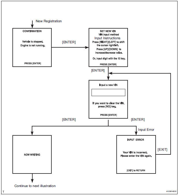
1. INPUT INSTRUCTIONS
- The general VIN input instructions using the intelligent tester are shown below:
- The arrow buttons (UP, DOWN, RIGHT and LEFT) and numerical buttons (0 to 9) are used to input the VIN.
- Cursor Operation To move the cursor around the tester screen, press the RIGHT and LEFT buttons.
- Alphabetical Character Input
- Press the UP and DOWN buttons to select the desired alphabetical character.
- Numerical Character Input
- Press the numerical button corresponding to the number that you want to input.
HINT: Numerical characters can be selected by using the UP and DOWN buttons.
- Correction
- When correcting the input character(s), put the cursor onto the character using the RIGHT and LEFT buttons.
- Select or input the correct character using the UP and DOWN buttons, or the numerical buttons.
- Finishing Input Operation
- Make sure that the input VIN matches the vehicle VIN after input.
- Press the ENTER button on the tester.
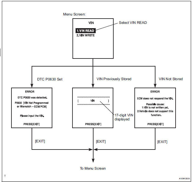
2. READ VIN (Vehicle Identification Number)
- The VIN reading process is shown in the flowchart below. Reading the VIN stored in the ECM is necessary when comparing it to the VIN provided with the vehicle.
- Read the VIN using the intelligent tester.
- Check the vehicle's VIN.
- Connect the intelligent tester to the DLC3.
- Turn the ignition switch to the ON position.
- Turn the tester ON.
- Enter the following menus: DIAGNOSIS / ENHANCED OBD II / VIN.
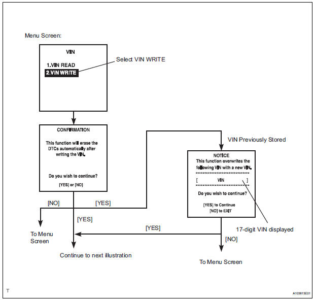
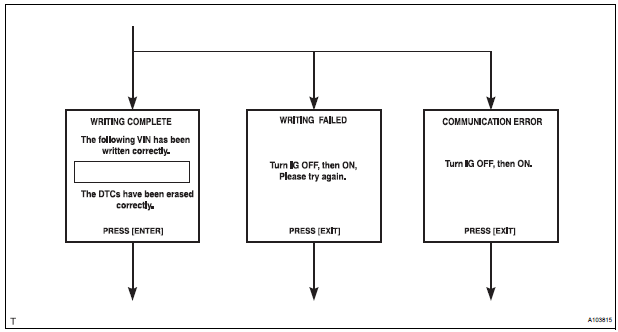
3. WRITE VIN
- The VIN writing process is shown in the flowchart below. This process allows the VIN to be input into the ECM. If the ECM is changed, or the ECM VIN and Vehicle VIN do not match, the VIN can be registered, or overwritten in the ECM by following this procedure.
- Write VIN using the intelligent tester.
- Connect the intelligent tester to the DLC3.
- Turn the ignition switch to the ON position.
- Turn the tester ON.
- Enter the following menus: DIAGNOSIS / ENHANCED OBD II / VIN.
 Basic inspection
When a malfunction is not confirmed by the DTC check,
troubleshooting should be carried out in all circuits
considered to be possible causes of the problem. In many
cases, by carrying out the basic ...
 Checking monitor status
The purpose of the monitor result (mode 06) is to allow
access to the results for on-board diagnostic monitoring tests
of specific components/systems that are not continuously
monitored. Examples a ...
Other materials:
Open in Curtain Shield Squib LH Circuit
DTC B1166/88 Open in Curtain Shield Squib LH Circuit
DESCRIPTION
The curtain shield squib LH circuit consists of the center airbag sensor
assembly and the curtain shield
airbag assembly LH.
The circuit instructs the SRS to deploy when deployment conditions are met.
DTC B1166/88 is recorde ...
Illumination Circuit
DESCRIPTION
Power is supplied to the radio receiver and steering pad switch illumination
when the light control switch is
in the TAIL or HEAD position.
WIRING DIAGRAM
INSPECTION PROCEDURE
NOTICE:
The vehicle is equipped with an SRS (Supplemental Restraint System) which
includes
compon ...
Fuel tank
Components
REMOVAL
1. DISCHARGE FUEL SYSTEM PRESSURE
(See page FU-1)
2. REMOVE CHARCOAL CANISTER PROTECTOR (See
page FU-30)
3. REMOVE REAR FLOOR NO. 2 CROSSMEMBER BRACE LH
(a) Remove the 2 bolts and the rear floor No. 2
crossmember brace LH.
4. REMOVE FUEL TANK FILLER HOSE COVER ...
