Toyota Sienna Service Manual: Installation
1. INSTALL SEAT POSITION AIRBAG SENSOR
- Check that the ignition switch is off.
- Check that the negative battery (-) terminal is disconnected.
CAUTION: After disconnecting the negative battery terminal, wait for at least 90 seconds before starting the operation.
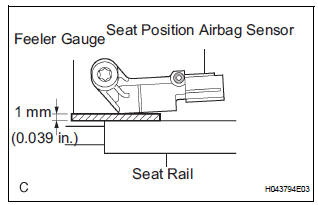
- Using a feeler gauge 1 mm (0.039 in.), install the seat position sensor.
NOTICE:
- If the seat position sensor has been dropped, or there are any cracks, dents or other defects in the case or connector, replace it with a new one.
- When installing the seat position sensor, be careful that the SRS wiring does not interfere with other parts and that it is not pinched between other parts.
HINT: Be sure that a clearance between the seat position sensor and the seat rail is within 0.6 mm (0.023 in.) to 1.4 mm (0.055 in.).
- Using a "torx" socket wrench (T30), tighten the
"torx" screw to install the seat position sensor.
Torque: 8.0 N*m (82 kgf*cm, 71 in.*lbf)
- Make sure that a clearance between the seat position sensor and the seat rail is within 0.6 mm (0.023 in.) to 1.4 mm (0.055 in.).
- Check that there is no looseness in the installation parts of the seat position sensor.
- Connect the connector to the seat position sensor.
2. INSTALL SEAT SLIDE POSITION SENSOR PROTECTOR
3. INSTALL FRONT SEAT CUSHION SHIELD ASSEMBLY (for Power Seat)
4. INSTALL SLIDE AND VERTICAL POWER SEAT SWITCH KNOB (for Power Seat)
5. INSTALL RECLINING POWER SEAT SWITCH KNOB (for Power Seat)
6. INSTALL FRONT SEAT CUSHION SHIELD LH (for Manual Seat)
7. INSTALL VERTICAL ADJUSTING HANDLE NO.2 (for Manual Seat)
8. INSTALL VERTICAL SEAT ADJUSTER KNOB CAP (for Manual Seat)
9. INSTALL RECLINING ADJUSTER RELEASE HANDLE LH (for Manual Seat)
10. INSTALL FRONT SEAT ASSEMBLY (for Manual Seat)
11. INSTALL FRONT SEAT ASSEMBLY (for Power Seat)
12. CONNECT CABLE TO NEGATIVE BATTERY TERMINAL
13. PERFORM INITIALIZATION
- Perform initialization.
HINT: Some systems need initialization when disconnecting the cable from the negative battery terminal.
14. INSPECT SLIDE ADJUSTER LOCK (for Manual Seat)
15. INSPECT POWER SEAT OPERATION (for Power Seat)
16. INSPECT SEAT HEATER OPERATION (w/ Seat Heater System)
17. INSPECT SRS WARNING LIGHT
- Inspect the SRS warning light
 Removal
1. PRECAUTION
CAUTION: Be sure to read "PRECAUTION" thoroughly before
servicing.
2. DISCONNECT CABLE FROM NEGATIVE BATTERY
TERMINAL
CAUTION:
Wait for 90 seconds after disconnecting th ...
 Occupant classification ECU
COMPONENTS
...
Other materials:
Rear Room Temperature Sensor Circuit
DESCRIPTION
This sensor detects the rear cabin temperature that is used as the basis for
temperature control and
sends a signal to the A/C amplifier.
WIRING DIAGRAM
INSPECTION PROCEDURE
1 READ VALUE OF INTELLIGENT TESTER
(a) Connect the intelligent tester to the DLC3.
(b) Turn the ign ...
Engine Coolant Temperature Circuit Range /
Performance Problem
DTC P0116 Engine Coolant Temperature Circuit Range /
Performance Problem
DESCRIPTION
Refer to DTC P0115
DTC No.
DTC Detection Condition
Trouble Area
P0116
ECTs as listed below are nearly same (2 trip detection
logic):
ECT when engine is start ...
Customizable features
Settings that can be changed using the audio system screen
Settings that can be changed using the multi-information display
Settings that can be changed by your Toyota dealer
Definition of symbols: O = Available, – = Not available
Gauges, meters and multi-information display (, 93)
...
