
Toyota Sienna Service Manual: Occupant classification ECU
COMPONENTS
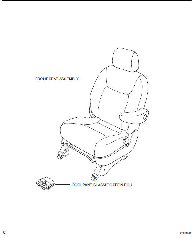
 Installation
1. INSTALL SEAT POSITION AIRBAG SENSOR
Check that the ignition switch is off.
Check that the negative battery (-) terminal is
disconnected.
CAUTION:
After disconnecting the ...
 On-vehicle inspection
1. INSPECT OCCUPANT CLASSIFICATION ECU
(VEHICLE NOT INVOLVED IN COLLISION)
Perform a diagnostic system check.
2. INSPECT OCCUPANT CLASSIFICATION ECU
(VEHICLE INVOLVED IN COLLISION)
...
Other materials:
Pre-collision seat belts (front seats of vehicles with pre-collision
system)
If the system determines that a collision is unavoidable, the front seat
belts will retract before the collision.
Emergency locking retractor (ELR)
The retractor will lock the belt during a sudden stop or on impact. It may
also
lock if you lean forward too quickly. A slow, easy motion wi ...
Installation
1. INSTALL HEADLIGHT ASSEMBLY
Connect the connectors.
Install the headlight assembly with the bolt and 3
screws.
2. INSTALL FRONT BUMPER ASSEMBLY
3. CONNECT CABLE TO NEGATIVE BATTERY
TERMINAL
4. VEHICLE PREPARATION FOR HEADLIGHT AIMING
5. PREPARATION FOR HEADLIGHT AIMI ...
Open in One Side of CAN Branch Line
DESCRIPTION
If 2 or more ECUs and/or sensors do not appear on the intelligent tester
"Communication Bus Check"
screen, one side of the CAN branch wire may be open. (One side of the CAN-H
[branch wire] / CAN-L
[branch wire] of the ECU and/or sensor is open.)
Symptom
...
