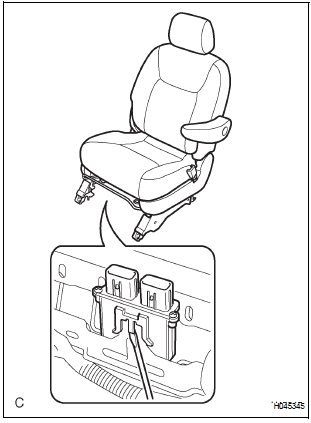
Toyota Sienna Service Manual: Installation
1. INSTALL OCCUPANT CLASSIFICATION ECU

- Check that the ignition switch is off.
- Check that the negative battery (-) terminal is
disconnected.
CAUTION: After disconnecting the negative battery terminal, wait for at least 90 seconds before starting the operation.
- Install the occupant classification ECU.
- Connect the 2 connectors to the occupant classification ECU.
NOTICE:
- If the occupant classification ECU has been dropped, or there are any cracks, dents or other defects in the case or connector, replace it with a new one.
- When installing the occupant classification ECU, be careful that the SRS wiring does not interfere with other parts and that it is not pinched between other parts.
2. INSTALL FRONT SEAT ASSEMBLY (for Manual Seat)
3. INSTALL FRONT RH SEAT ASSEMBLY (for Power Seat)
4. CONNECT CABLE TO NEGATIVE BATTERY TERMINAL
5. PERFORM INITIALIZATION
- Perform initialization.
HINT: Some systems need initialization when disconnecting the cable from the negative battery terminal.
6. INSPECT SLIDE ADJUSTER LOCK (for Manual Seat)
7. INSPECT POWER SEAT OPERATION (for Power Seat)
8. INSPECT SEAT HEATER OPERATION (w/ Seat Heater System)
9. INSPECT SRS WARNING LIGHT
- Inspect the SRS warning light
 Removal
1. PRECAUTION
CAUTION:
Be sure to read "PRECAUTION" thoroughly before servicing.
2. DISCONNECT CABLE FROM NEGATIVE BATTERY
TERMINAL
CAUTION:
Wait for 90 seconds after disconnecting the ...
 Seat belt
...
Other materials:
Removal
1. REMOVE ROOF HEADLINING ASSEMBLY
2. REMOVE SLIDING ROOF SIDE GARNISH LH
Disengage the 3 claws.
Disengage the rear clip.
Disengage the front clip.
Remove the slide garnish by pulling it rearward.
3. REMOVE SLIDING ROOF SIDE GARNISH RH
HINT:
Use the same procedures described abov ...
Stuck in Deceleration Sensor
DESCRIPTION
The yaw rate sensor and deceleration sensor signal is sent to the skid
control ECU through the CAN
communication system. When there is a malfunction in the communication, it will
be detected by the
diagnosis function.
WIRING DIAGRAM
INSPECTION PROCEDURE
HINT:
When ...
Differential oil
Adjustment
1. INSPECT DIFFERENTIAL OIL
(a) Stop the vehicle on the level place.
(b) Remove the differential filler plug and gasket.
(c) Check that the oil surface is within 5 mm (0.20 in.)
from the lowest position of the inner surface of the
differential filler plug opening.
NOTICE:
...
