Toyota Sienna Service Manual: Installation
1. INSTALL VVT SENSOR (for Bank 2 Exhaust Side)
- Install the VVT sensor with the bolt.
Torque: 10 N*m (102 kgf*cm, 7 ft.*lbf)
- Connect the VVT sensor connector.
2. INSTALL VVT SENSOR (for Bank 2 Intake Side)
- Install the VVT sensor with the bolt.
Torque: 10 N*m (102 kgf*cm, 7 ft.*lbf)
- Connect the VVT sensor connector.
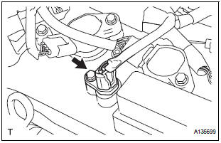
3. INSTALL VVT SENSOR (for Bank 1 Exhaust Side)
- Install the VVT sensor with the bolt.
Torque: 10 N*m (102 kgf*cm, 7 ft.*lbf)
- Connect the VVT sensor connector.
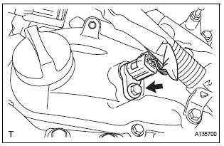
4. INSTALL VVT SENSOR (for Bank 1 Intake Side)
- Install the VVT sensor with the bolt.
Torque: 10 N*m (102 kgf*cm, 7 ft.*lbf)
- Connect the VVT sensor connector.
5. INSTALL INTAKE AIR SURGE TANK ASSEMBLY
6. INSTALL AIR CLEANER CASE SUB-ASSEMBLY
7. INSTALL AIR CLEANER CAP SUB-ASSEMBLY
8. INSTALL NO. 1 AIR CLEANER INLET
9. INSTALL NO. 2 AIR CLEANER INLET
10. ADD ENGINE COOLANT
11. INSPECT FOR ENGINE COOLANT LEAK
12. INSPECT FOR ENGINE OIL LEAK
13. INSTALL V-BANK COVER SUB-ASSEMBLY
14. INSTALL FRONT OUTER COWL TOP PANEL SUBASSEMBLY
15. INSTALL WINDSHIELD WIPER MOTOR ASSEMBLY
 Removal
1. REMOVE WINDSHIELD WIPER MOTOR ASSEMBLY
2. REMOVE FRONT OUTER COWL TOP PANEL SUBASSEMBLY
3. DRAIN ENGINE COOLANT
4. REMOVE V-BANK COVER SUB-ASSEMBLY
5. REMOVE NO. 2 AIR CLEANER INLET
6. REMOVE ...
 Crankshaft position sensor
COMPONENTS
...
Other materials:
If a warning light turns on
or a warning buzzer
sounds
Calmly perform the following actions if any of the warning lights
comes on or flashes. If a light comes on or flashes, but then
goes off, this does not necessarily indicate a malfunction in the
system. However, if this continues to occur, have the vehicle
inspected by your Toyota dealer.
Warnin ...
Solar Sensor Circuit (Driver Side)
DESCRIPTION
The solar sensor, which is installed on the upper side of the instrument
panel, detects sunlight and
controls the air conditioning in AUTO mode. The output voltage from the solar
sensor varies according to
the amount of sunlight. When the sunlight increases, the output voltage ...
Side Airbag Sensor Assembly LH Circuit Malfunction
DTC B1141/33 Side Airbag Sensor Assembly LH Circuit Malfunction
DESCRIPTION
The side airbag sensor LH circuit consists of the center airbag sensor
assembly and side airbag sensor
LH.
If the center airbag sensor assembly receives signals from the side airbag
sensor LH, it judges whether or
...
