Toyota Sienna Service Manual: Removal
1. REMOVE WINDSHIELD WIPER MOTOR ASSEMBLY
2. REMOVE FRONT OUTER COWL TOP PANEL SUBASSEMBLY
3. DRAIN ENGINE COOLANT
4. REMOVE V-BANK COVER SUB-ASSEMBLY
5. REMOVE NO. 2 AIR CLEANER INLET
6. REMOVE NO. 1 AIR CLEANER INLET
7. REMOVE AIR CLEANER CAP SUB-ASSEMBLY
8. REMOVE AIR CLEANER CASE SUB-ASSEMBLY
9. REMOVE INTAKE AIR SURGE TANK ASSEMBLY
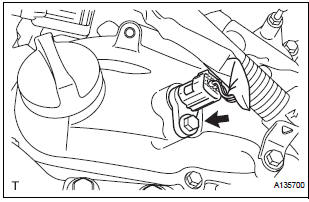
10. REMOVE VVT SENSOR (for Bank 1 Intake Side)
- Disconnect the VVT sensor connector.
- Remove the bolt and VVT sensor.
11. REMOVE VVT SENSOR (for Bank 1 Exhaust Side)
- Disconnect the VVT sensor connector.
- Remove the bolt and VVT sensor.
12. REMOVE VVT SENSOR (for Bank 2 Intake Side)
- Disconnect the VVT sensor connector.
- Remove the bolt and VVT sensor.
13. REMOVE VVT SENSOR (for Bank 2 Exhaust Side)
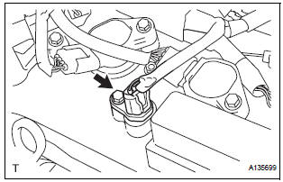
- Disconnect the VVT sensor connector.
- Remove the bolt and VVT sensor.
 On-vehicle inspection
1. CHECK VVT SENSOR OUTPUT VOLTAGE
Turn the ignition switch to the ON position.
Check the voltage between the specified terminal
and body ground.
Standard voltage
While turning ...
 Installation
1. INSTALL VVT SENSOR (for Bank 2 Exhaust Side)
Install the VVT sensor with the bolt.
Torque: 10 N*m (102 kgf*cm, 7 ft.*lbf)
Connect the VVT sensor connector.
2. INSTALL VVT ...
Other materials:
Exhaust gas precautions
Harmful substance to the human body is included in exhaust
gases if inhaled.
WARNINGExhaust gases include harmful carbon monoxide (CO),
which is colorless and
odorless. Observe the following precautions.
Failure to do so may cause exhaust gases enter the vehicle and may lead
...
Removal
1. REMOVE REAR WHEEL
2. REMOVE EXHAUST PIPE ASSEMBLY
HINT:
Perform this procedure only when removing the RH side.
(See page EX-8)
3. REMOVE REAR SPEED SENSOR LH
HINT:
(See page DS-21)
4. REMOVE REAR AXLE SHAFT NUT LH
HINT:
(See page DS-21)
5. REMOVE REAR DRIVE SHAFT ASSEMBLY LH
HINT:
...
Installation
1. INSTALL BRAKE ACTUATOR
NOTICE:
Do not remove the hole plugs before connecting the
brake tubes. New actuators are filled with brake
fluid.
(a) Install the brake actuator assembly with the 2 nuts.
Torque: 5.4 N*m (55 kgf*cm, 48 in.*lbf)
2. INSTALL BRAKE ACTUATOR WITH BRACKET
(a) Insta ...
